Map Configuration
Accurate maps can significantly improve the efficiency of subsequent deployments and the accuracy of positioning, so this should be given due attention.
- Ensure that the map matches the actual environment
- Make sure the map is the correct size; measure its length and width in several places and compare them with the dimensions shown on the map.
- Ensure that the coordinate mapping of the map is accurate after it is loaded into the software
- In multi-map scenarios, it is essential to ensure that the relative positions of different maps are correct. Since nearby base stations will receive signals from nearby locations, incorrect relative map positions are equivalent to incorrect base station coordinates, which can severely affect positioning accuracy. For example, in a building where multiple floors correspond to multiple maps, the origin and elevation of each map must align with reality. If the floor-to-floor height is 5 meters, then the first floor should be at 0 meters, the second floor at 5 meters, and the third floor at 10 meters....
- For buildings or maps that are already quite far apart, their relative positions can be disregarded; they can be treated as independent positioning systems that do not affect one another.
Single Map Configuration
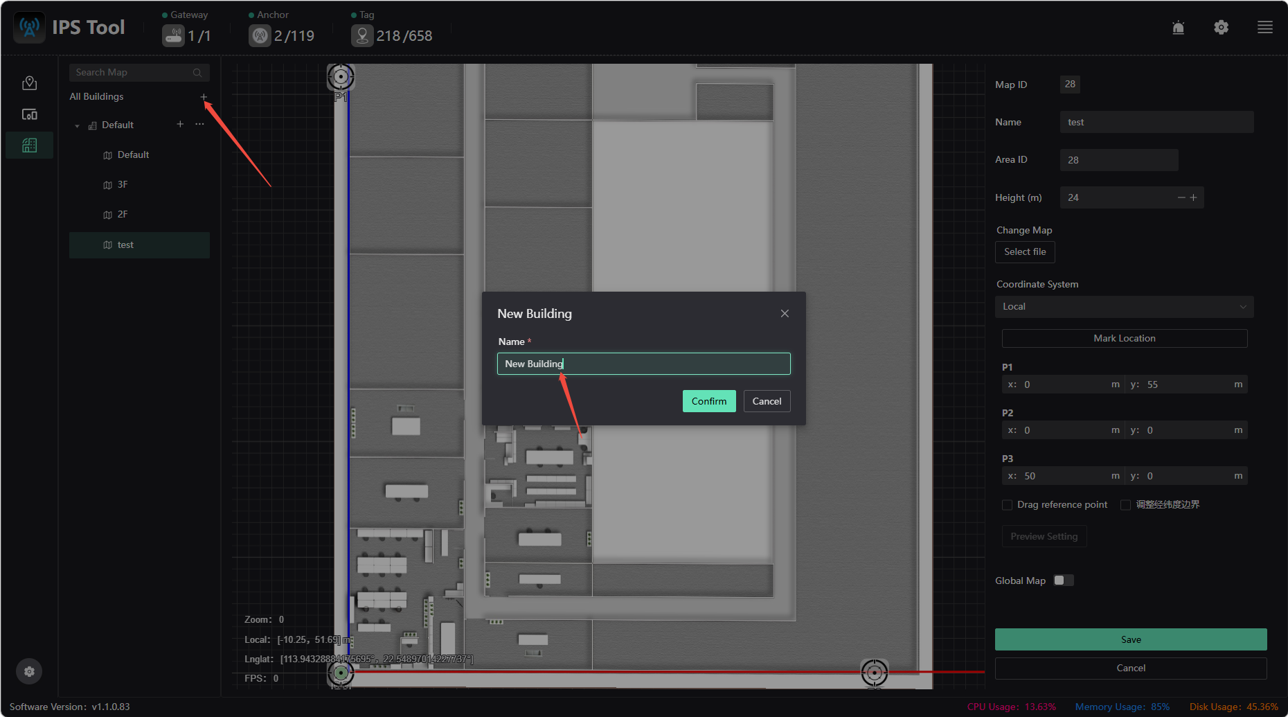
1.Click “Map Management” on the left, add a map, select the map file, and set the name and elevation.
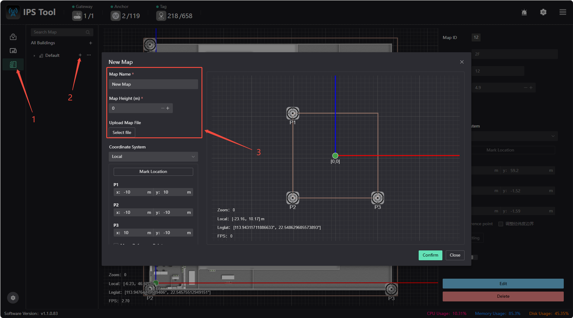
2.Select the newly added map, which has three reference points: P1, P2, and P3. You need to configure the actual corresponding locations of these three reference points to enable map coordinate mapping.
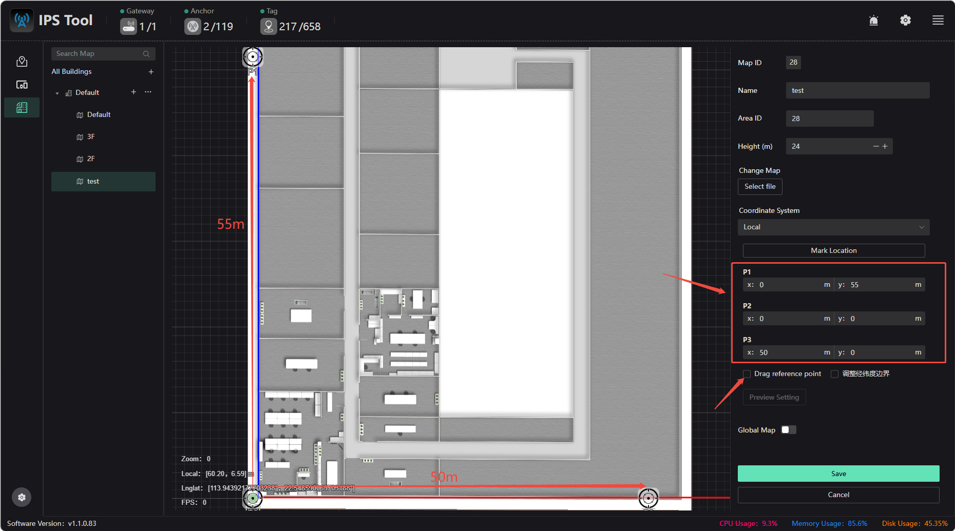
(1) Check the “Move Reference Points” box, then drag the three reference points to the building feature points. These points should be easily accessible for determining actual distances (e.g., through on-site measurements or distances known from CAD drawings).
(2) In the figure, P2 is used as the coordinate origin, with P1 placed in the upper-left corner and P3 in the lower-right corner. Given that the actual distance between P2 and P1 is 55 m and the actual distance between P2 and P3 is 50 m, set the coordinates as follows: P1(0, 55), P2(0, 0), P3(50, 0)
(3) After correctly entering the coordinates of the three reference points, the aspect ratio of the map is automatically determined (provided that the imported map is accurately drawn and the reference point coordinates are entered correctly), thereby achieving coordinate mapping for the entire map.
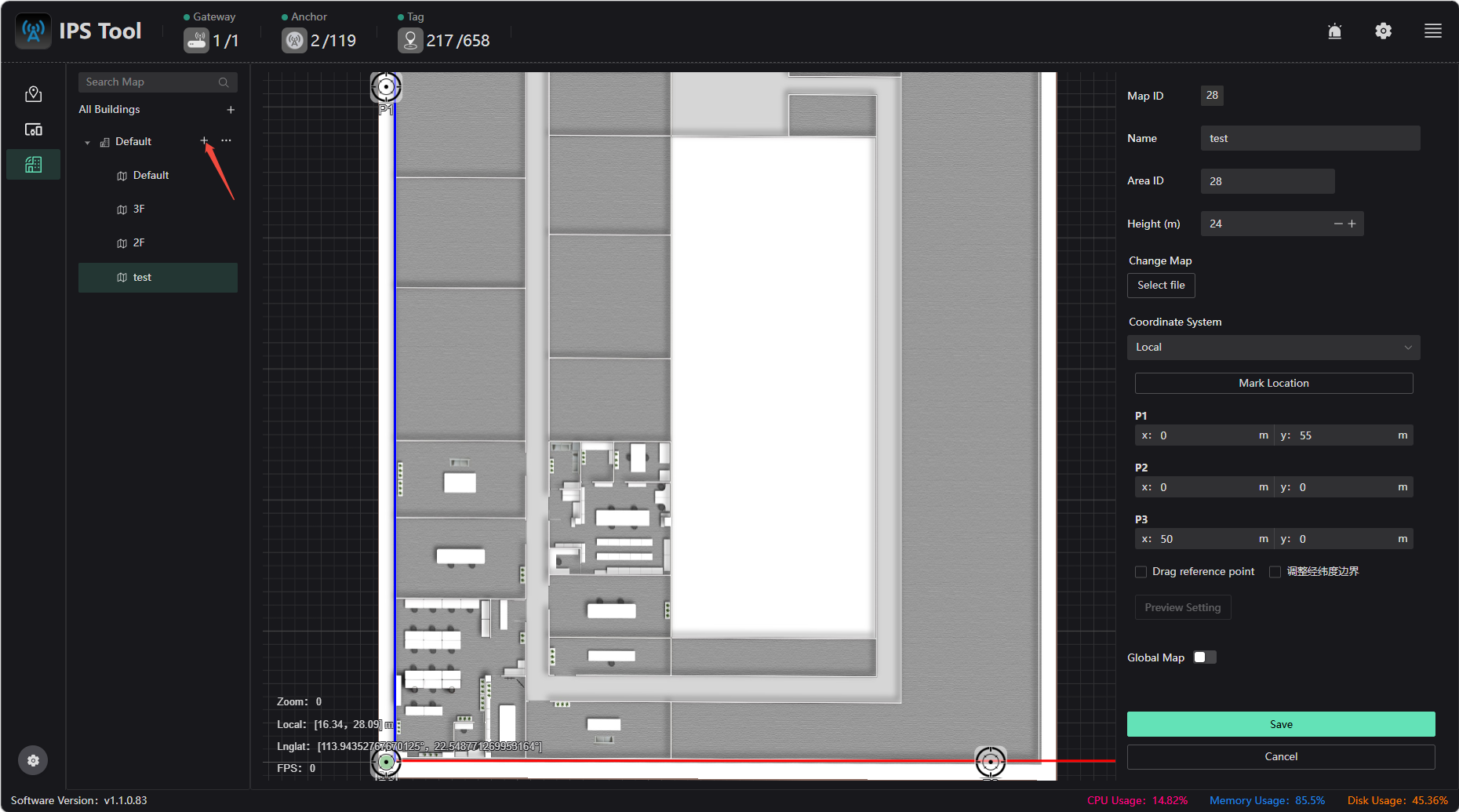
Multi-floor Map Configuration
Simply click “Add New Map” and select the map files for each floor to add and configure them accordingly.
Multi-Building Map Configuration
Click “All Buildings” under “Map Management,” then click the “Add Building” button to add a new building. For specific instructions on adding a map after adding a building, please refer toSingle Map Configuration
Map Configuration Examples
1.Add a Map:
Click “Map Management” on the left, then click “Add Map.” Enter a map name, configure the map's actual height above ground level, and import the map file (JPG or PNG).
2.Configuring Reference Point Coordinates:
As shown in the figure below: Use P2 as the origin, place P1 at the top-left corner of the map, and place P3 at the bottom-right corner of the map. The actual distance between P2 and P1 is 55m. and the actual distance between P2 and P3 is 50m. Set P1 to (0, 55), P2 to (0, 0), and P3 to (50, 0). Once the coordinates of these three reference points are correctly entered, the map’s aspect ratio will be set correctly (provided the imported map is accurate and the reference point coordinates are correct), enabling full-map coordinate mapping.
3.Verify that the map scale is correct:
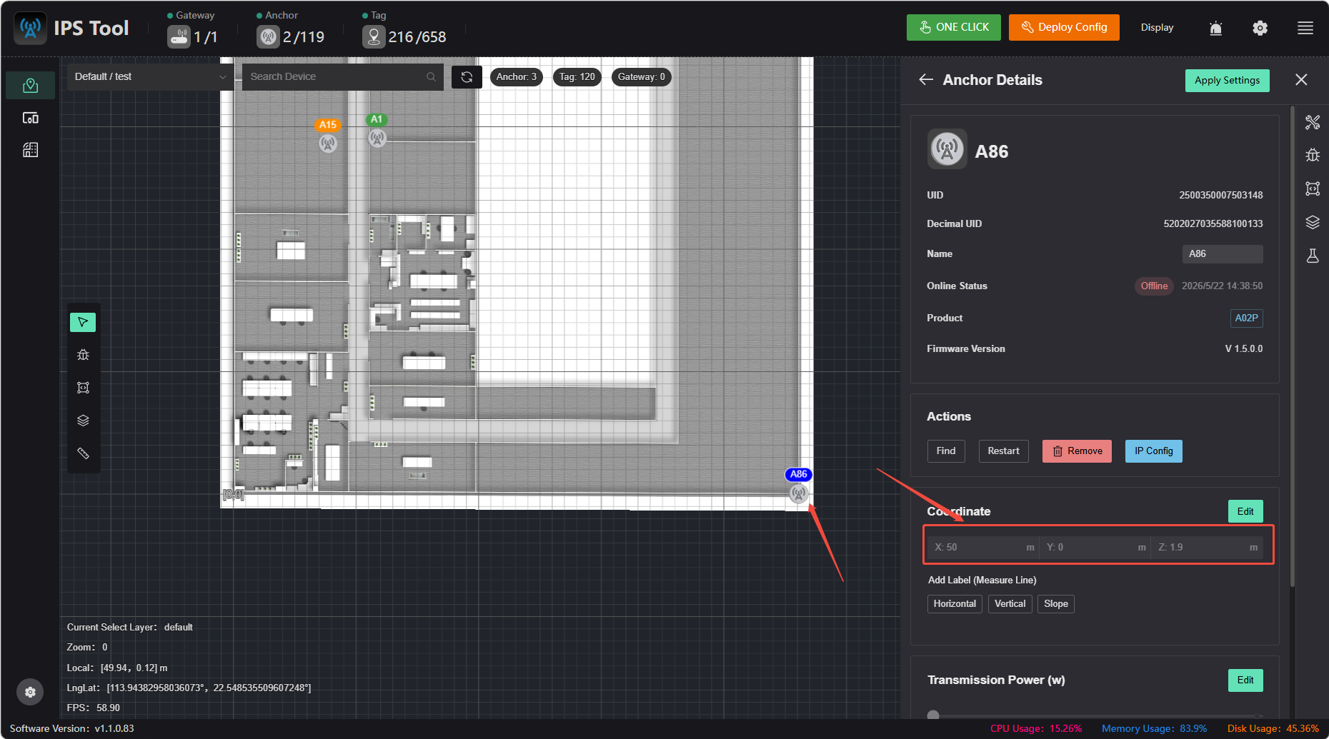
Method 1: Use known reference points/anchors
Example: If base station A2 is located at P3, A2 should be displayed as (50, 0). If this is correct, it indicates that the mapping is accurate, and the coordinates of other buildings are also correct.
Method 2: Verification Using Random Point Coordinates
Click on any architectural feature point on the map with the mouse, record the coordinates, and then compare them with the distance from that point to the origin as shown on the CAD drawing or measured on-site.
Method 3: Verification Using the Distance Between Two Known Points
Record the coordinates of two architectural feature points on the map, calculate the distance between them, and compare it with the distance shown on the CAD drawing or measured on-site.
⚠️ Note
The above verification is only meaningful if the map is accurately drawn and the reference point coordinates are entered correctly.
Once you have confirmed that the mapping is correct, you can use the Coordinate Measurement Method to quickly and manually obtain the coordinates of other base stations.
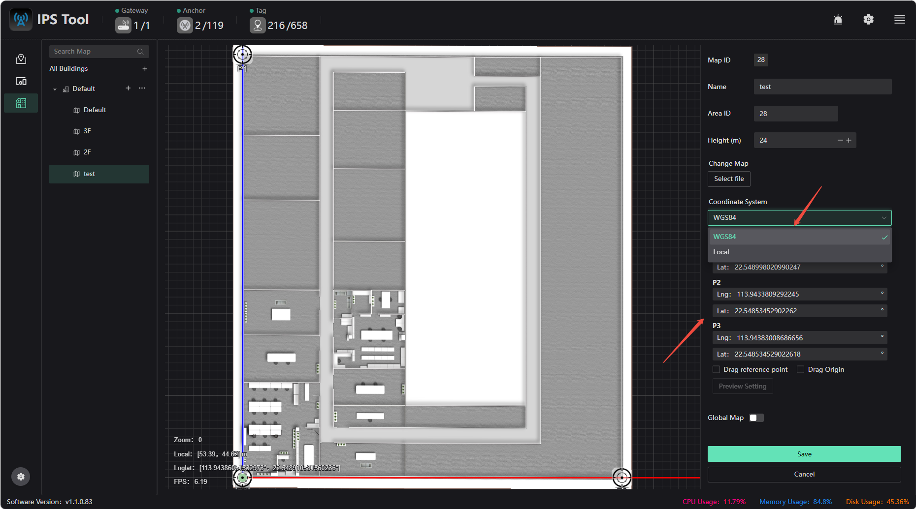
Latitude and Longitude Configuration and Coordinate Transformation
You can configure latitude and longitude to associate the local coordinate system of the indoor map with the WGS84 coordinate system. By entering three reference points (P1, P2, and P3) with known latitude and longitude values, the software can automatically establish a transformation relationship between the local coordinate system and the WGS84 coordinate system
Latitude and Longitude Configuration Steps:
- Select Reference Points: Choose three distinct and easily identifiable locations on the indoor map as reference points (e.g., wall corners, columns, access control centers). Ensure these three points do not lie on the same line and cover the entire work area as much as possible to improve conversion accuracy.
- Measure Latitude and Longitude: Use a high-precision GPS receiver, total station, or known surveying data to obtain the precise latitude and longitude (WGS84 coordinate system) of these three reference points.
- Enter Latitude and Longitude Information: Select the manual input mode and enter the latitude and longitude information for the three reference points.
Coordinate Transformation: After saving the above configuration, check the “Map Information” box to obtain the new transformation matrix information:
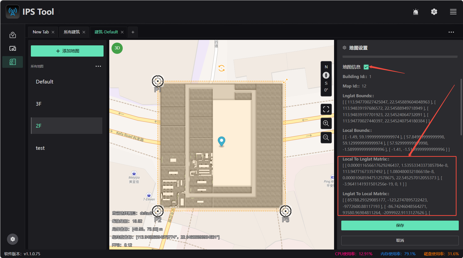
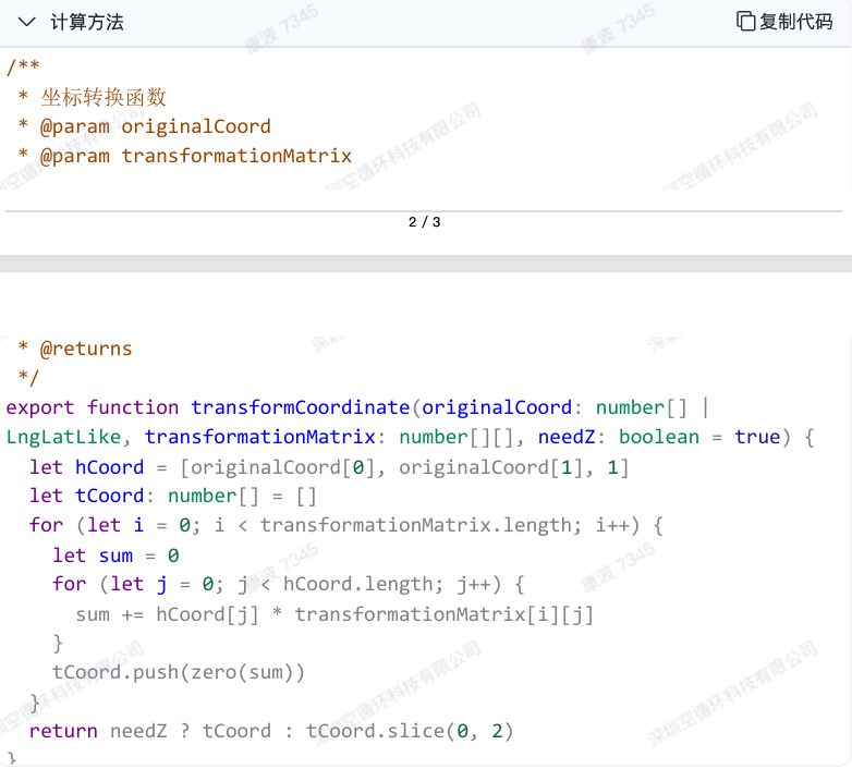
Coordinate transformation involves converting the local coordinates output by the label into latitude and longitude coordinates, which requires calculation using the coordinate transformation matrix. The transformation matrix obtained in the first step, the [Local To Lnglat Matrix], is a 2×3 matrix. Multiplying the local coordinates by this matrix yields the transformed latitude and longitude coordinates. The calculation method is as follows:
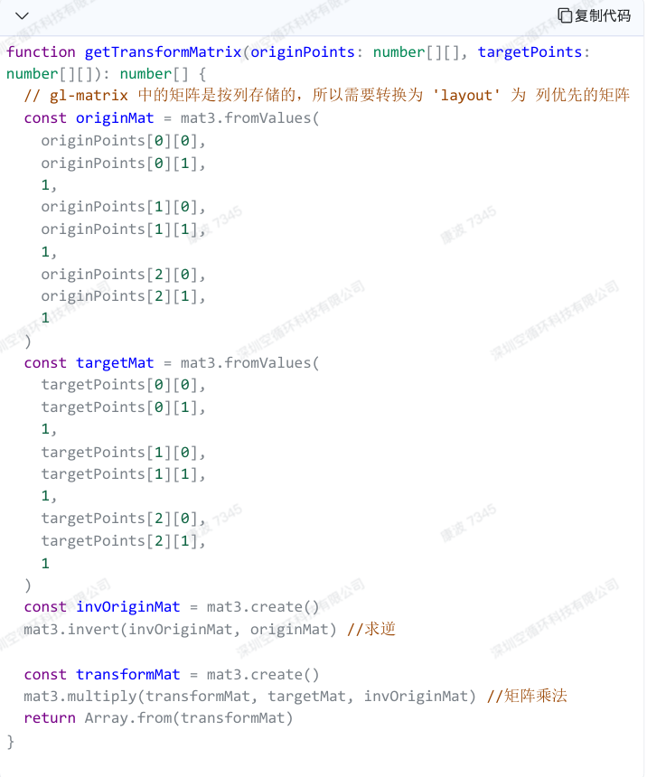
Calculating the Transformation Matrix:
● Place the three origin points [x, y] into a 3×3 matrix (each column represents the x and y coordinates of a point) [x, y, 1];
● Similarly, place the three target points into a 3×3 matrix;
● Compute the inverse of the originMat matrix to obtain invOriginMat;
● Multiply invOriginMat by targetMat to obtain the final transformation matrix M
sidebar_position: 7 id: system-configuration title: System Configuration
System Configuration
Process 1 [Map Configuration]
Map Configuration
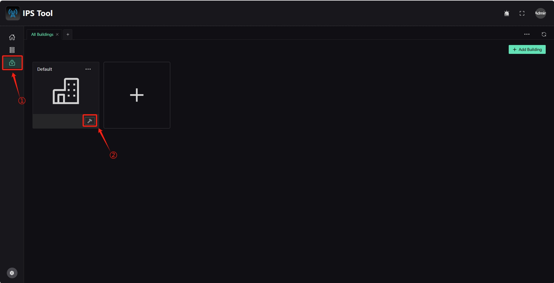
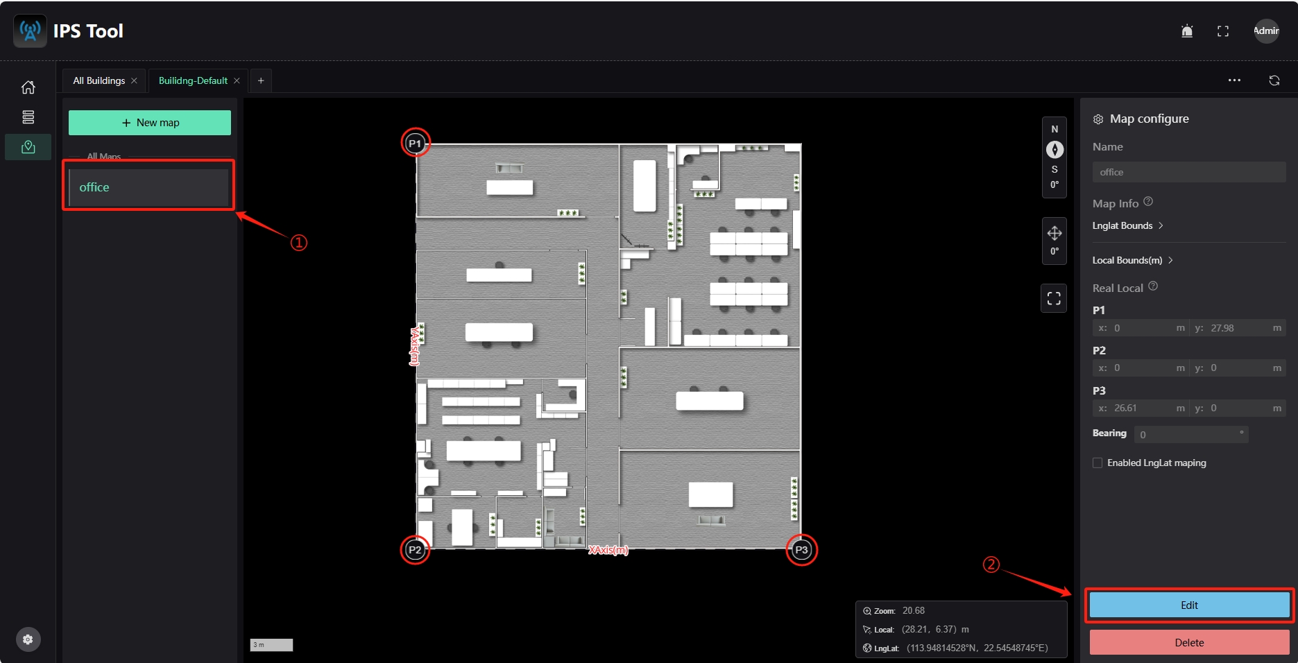
Click the "Map Management" icon in the left column and click the "Edit Map" option in the Default box.
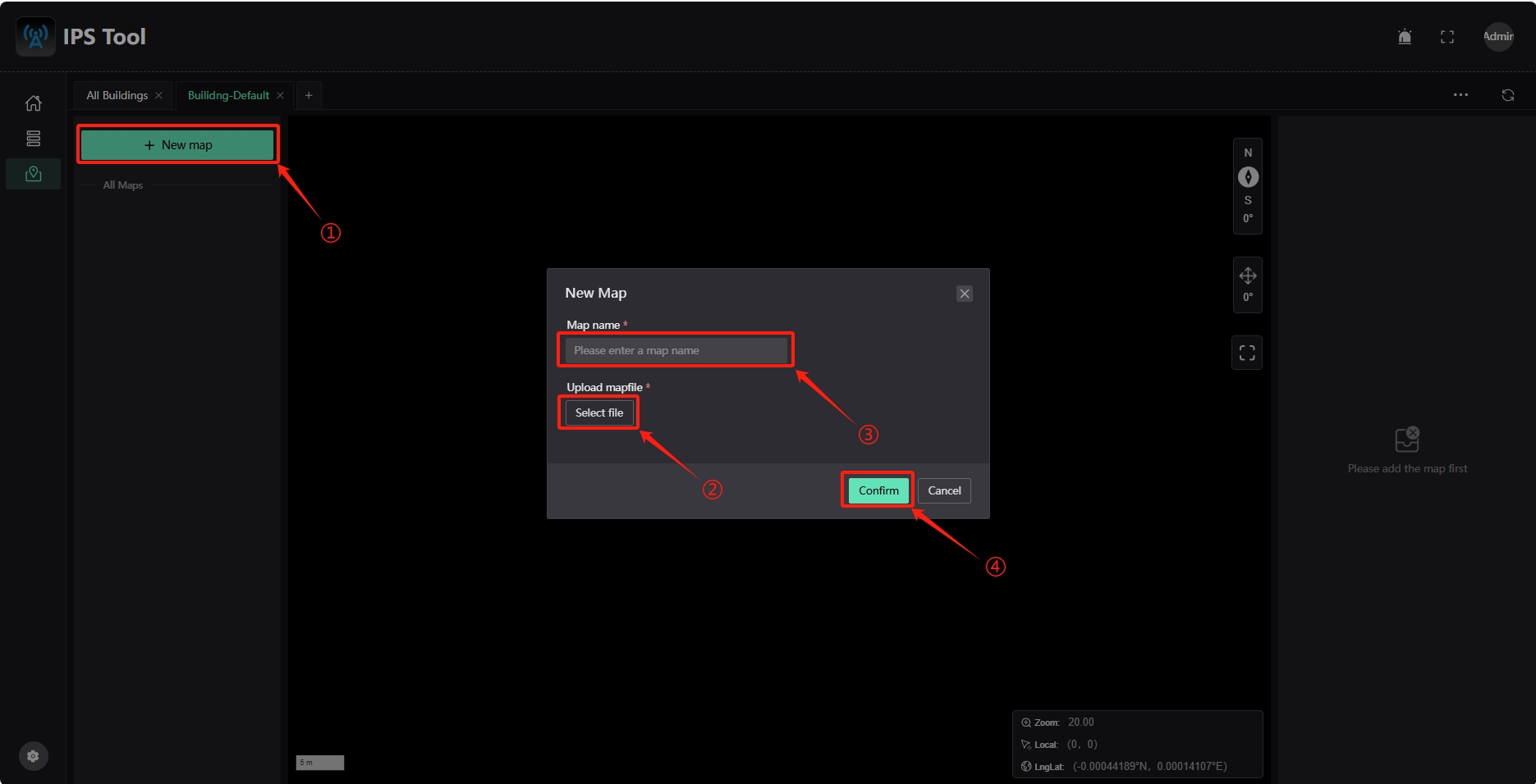
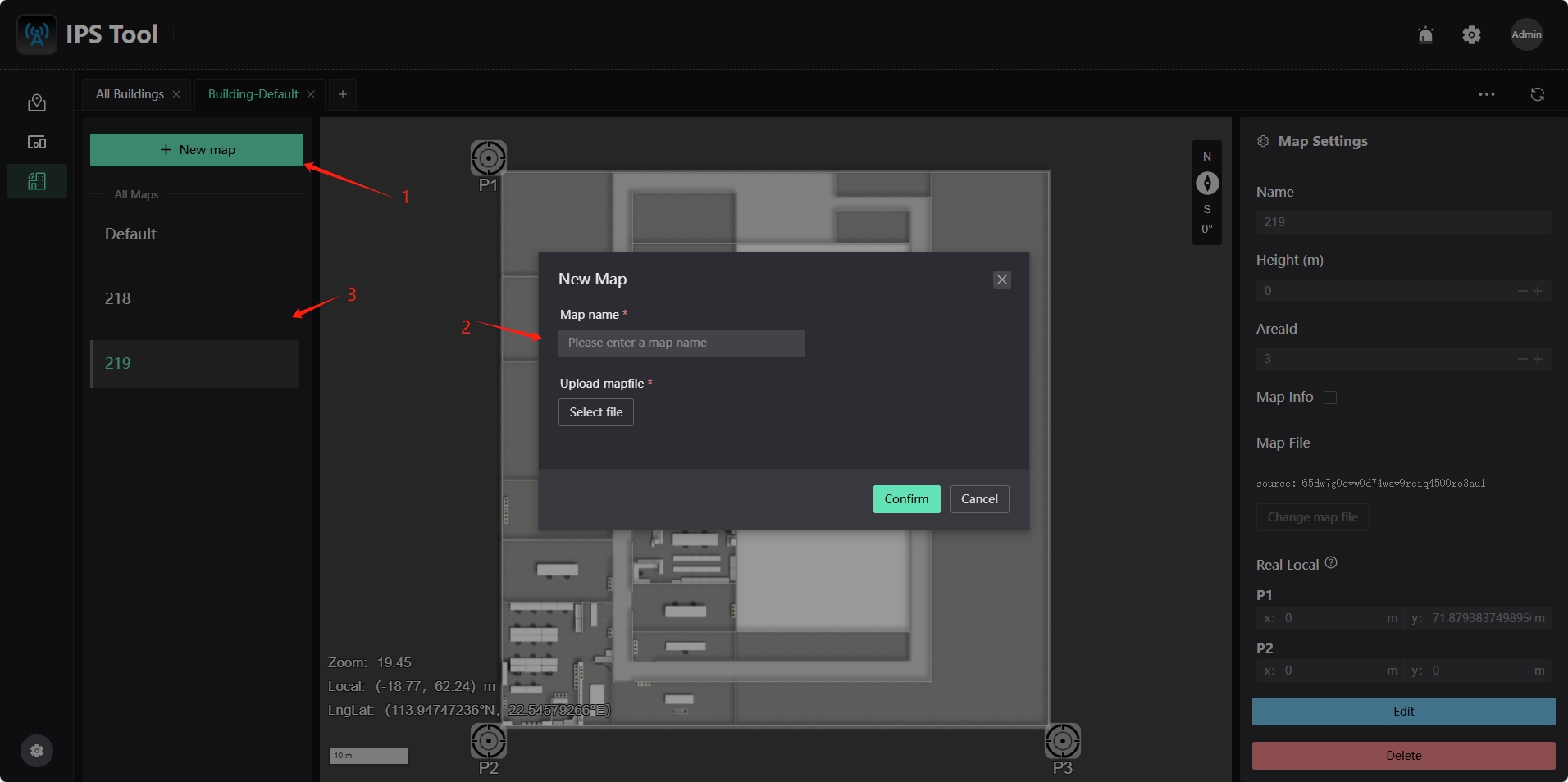
Click the "+ New map" option, select the map file to be added (JPG or PNG format), enter the map name, and click "Confirm".
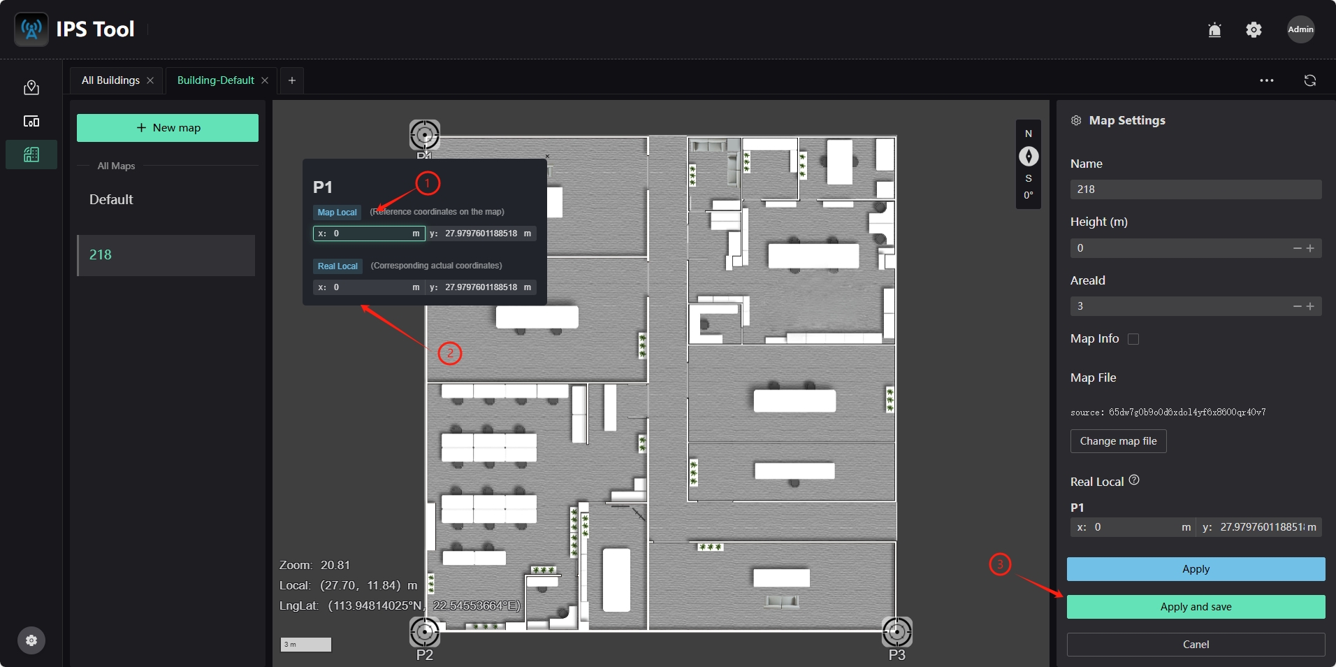
Select the newly added map name to see the newly added map. Three reference points "P1", "P2" and "P3" will appear on the map interface. You can configure the actual corresponding positions of these three reference points to achieve map coordinate mapping. Click the "Edit" button on the right to enter the editing state.
In the editing state, click the "P1" reference point on the map to edit the coordinate value of the current coordinate "Map Local" and the coordinate value of the actual coordinate "Real Local". After editing, click the "Apply and save" button in the lower right corner to apply and save the current operation. The same applies to "P2" and "P3".
Multi-Floor Map Configuration
Click the "+ New map" option, select the map file to be added (JPG or PNG format), enter the map name, and click "Confirm" to complete the map addition. If there are multiple floors, you can continue to click the "+ New map" option to select map files for different floors and add them accordingly.
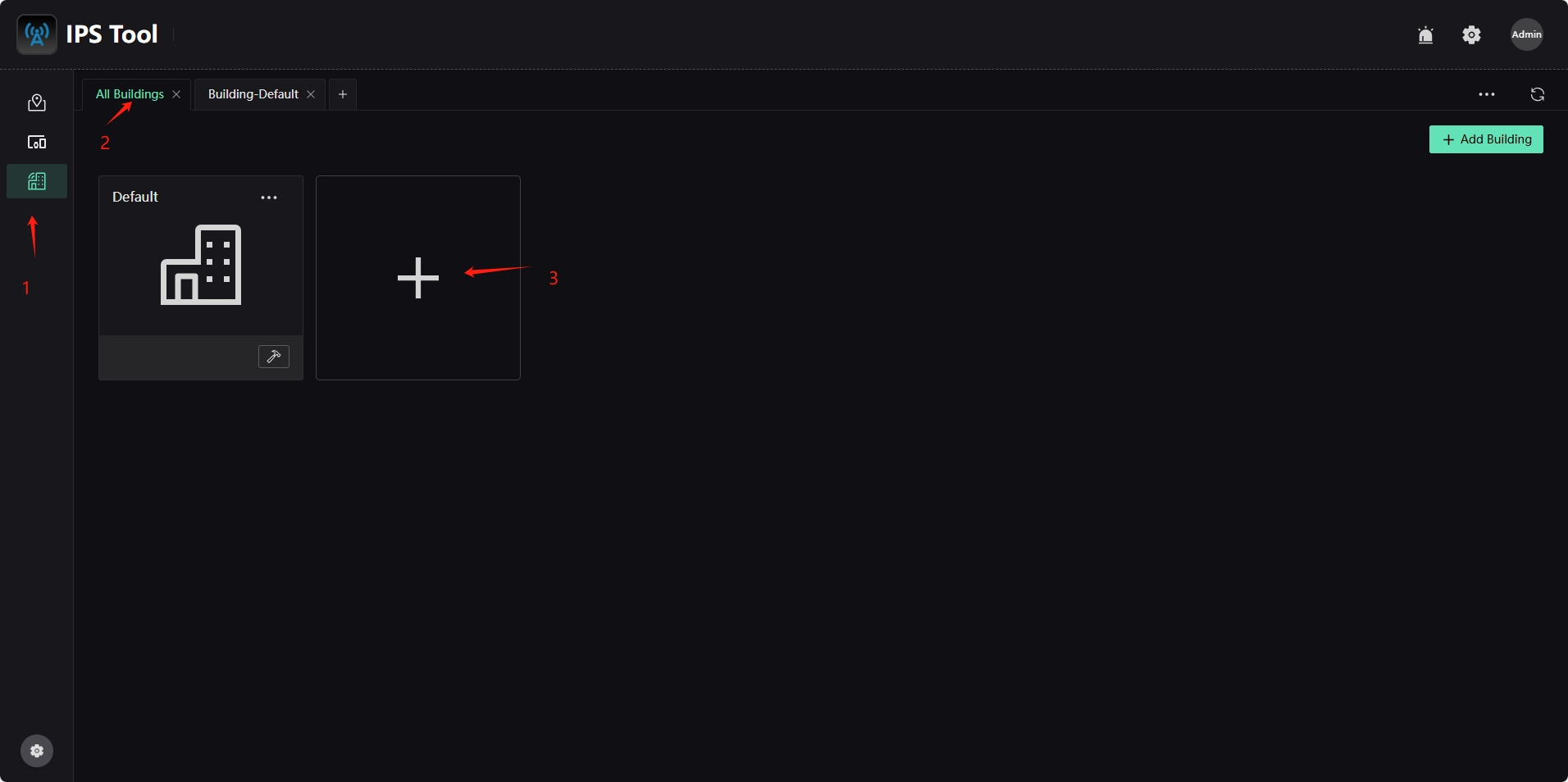
Multi-Building Map Configuration
Click the "Map Management" icon in the left column, click the "All Buildings" option, in the pop-up interface, click the blank "+" in the interface to add multiple buildings, enter the building name in the pop-up dialog, click the Submit button to save the configuration, and after adding, click the "Edit Map" button to add a map. For specific operations, please refer to "Map Configuration".
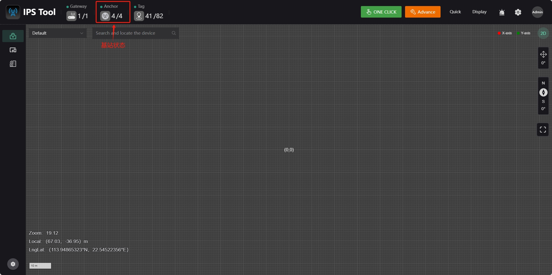
Process 2 [Server and Anchor Settings]
(1). Connect the server and IPS positioning anchor to the same local area network.
(2). Change the server IP address to 192.168.xx.254 (the default address of the anchor is 192.168.xx.254). If the number of anchor is displayed in the anchor position of the system main interface status bar, it means that the device has been successfully connected. Otherwise, you need to check whether the current network status is set correctly.
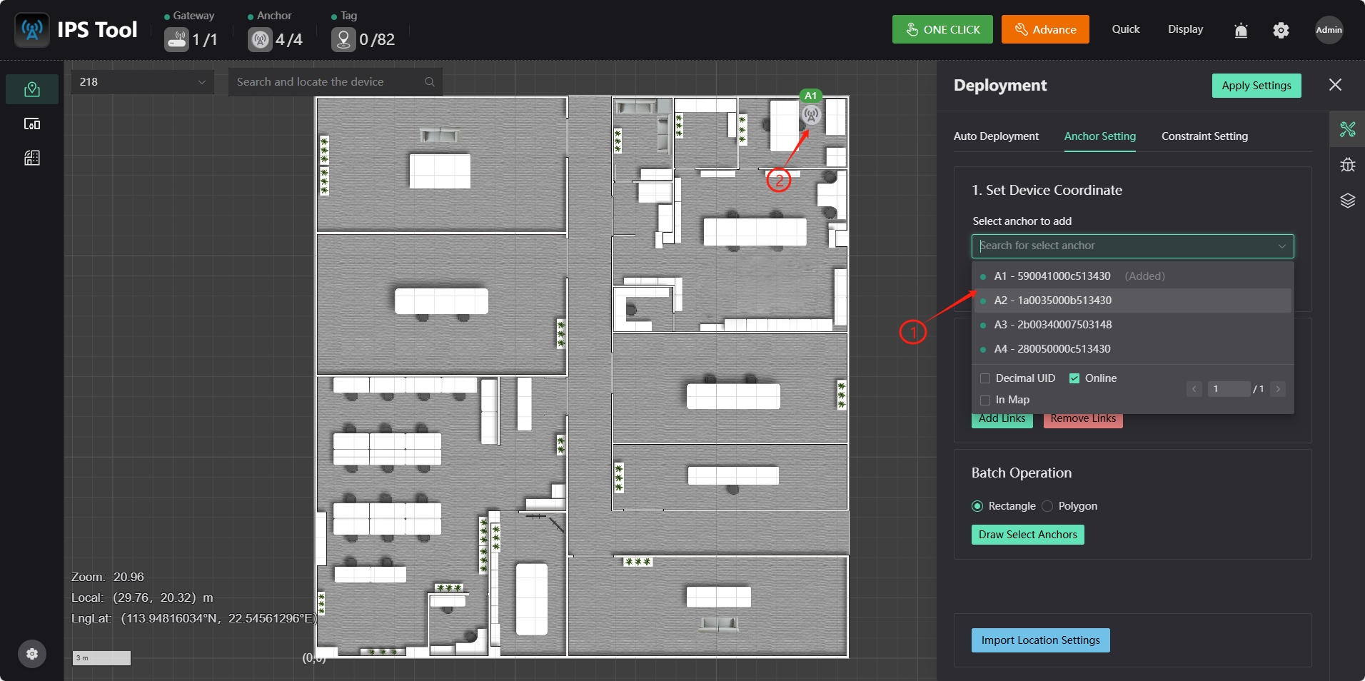
Process 3 [Anchor deployment]
Click the drop-down box in the upper left corner of the system main interface to select the map where the anchor needs to be deployed. Click the "Advance" button in the upper right corner to enter the "Deployment" page. Select the anchor to be deployed in the "Set Device Coordinate" configuration drop-down box.

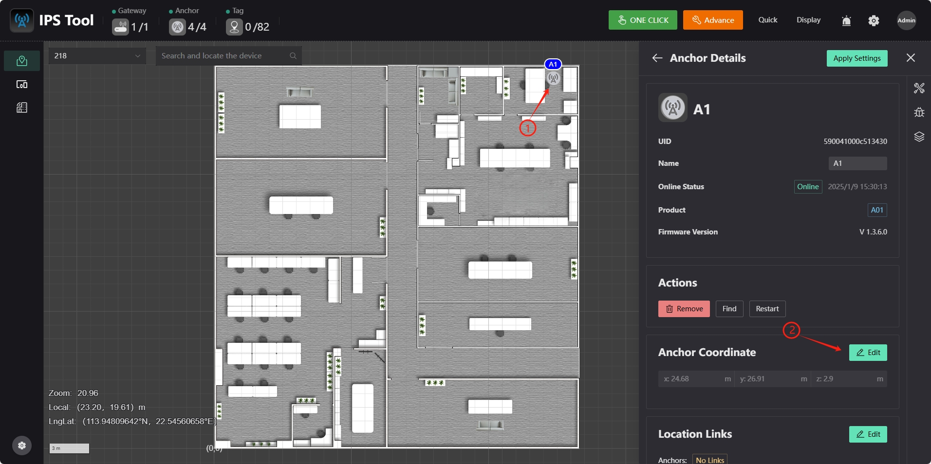
Process 4 [Anchor Configuration]
Select the anchor you want to add in the "Set Device Coordinate" configuration drop-down box, move the cursor to the map location corresponding to the anchor, and click the left mouse button to add the anchor.
Click the right side of the anchor icon to pop up the anchor device information box. Click "Edit" to correct the anchor coordinates. After the modification is completed, click the "Save" button to complete the modification. Click the Apply Settings button in the upper right corner to save the anchor location information.