Hardware Installation
1. Overall Architecture
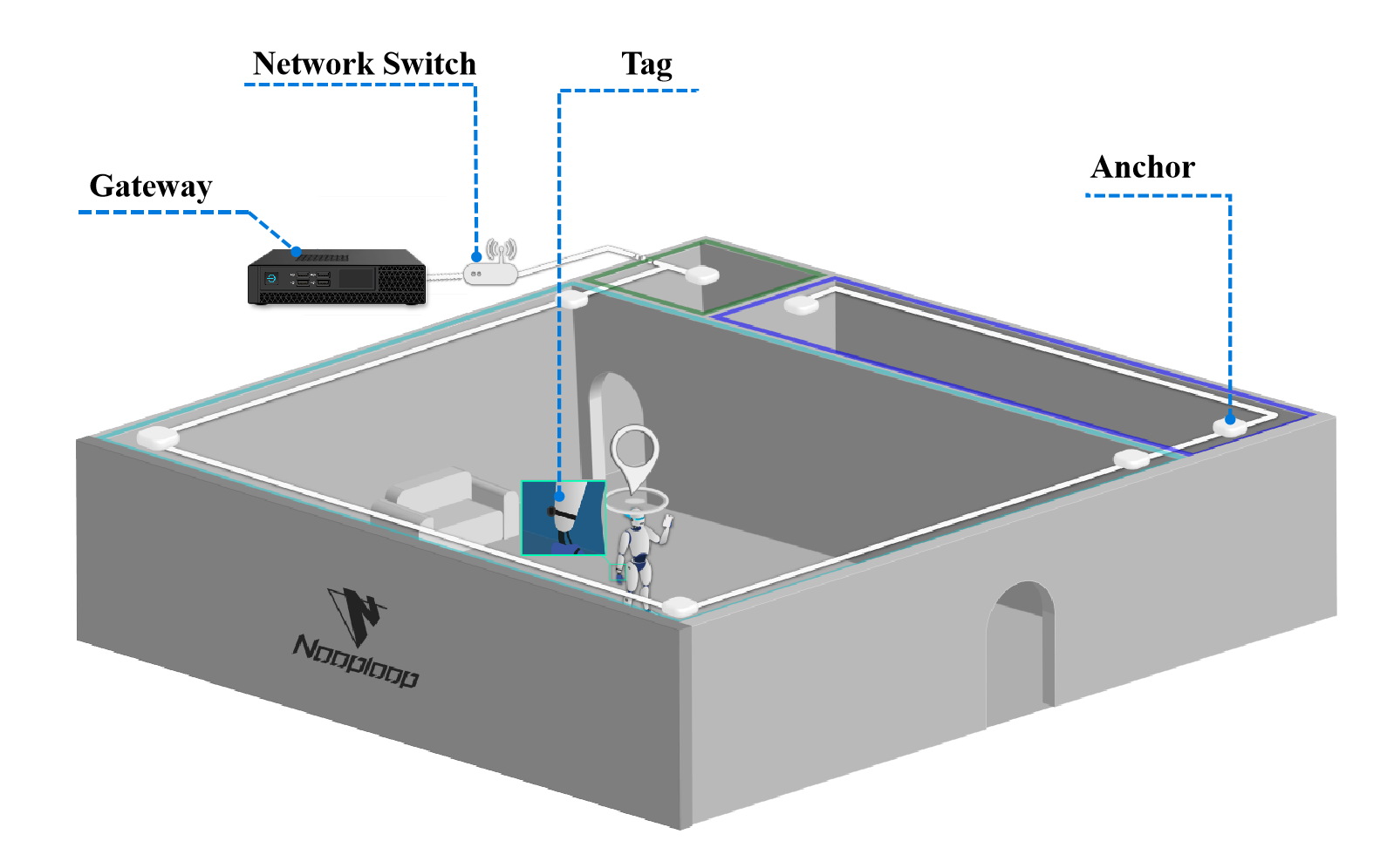
A complete IPS system requires the following hardware
| Hardware | Require | Suggested Links |
|---|---|---|
| Gateway | Nooploop Standard Product | / |
| Switch | 1000M POE switch | Click to view |
| Network cable | Category 5e network cable | Click to view |
| Anchor | Nooploop supplies standard base stations | / |
| Tag | Nooploop standard products, third-party label supplier | / |
2. Network Topology

RJ45 network cables, POE switches and gateways are usually used for network deployment. The anchor are powered by POE. At the same time, the anchor can be connected in cascade mode, with a maximum of 6 cascaded units supported.
3. Anchor Installation
A02, A02M anchor - ceiling installation
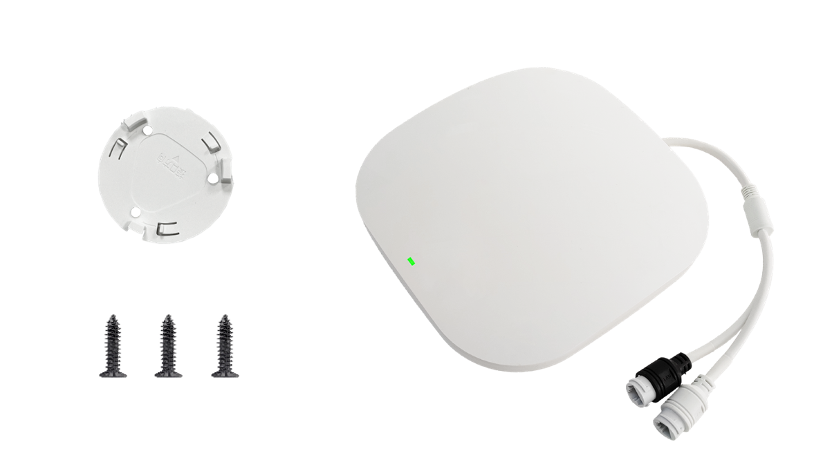 (1) Prepare the anchor, chassis, and self-tapping screws | 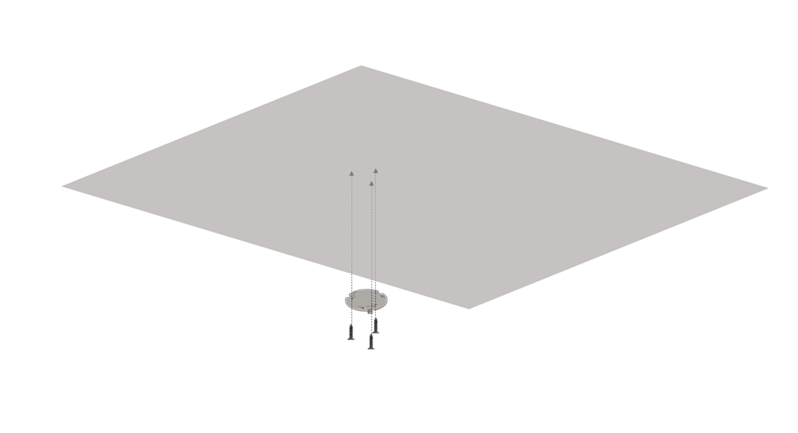 (2) The anchor chassis is fixed on the ceiling |
|---|---|
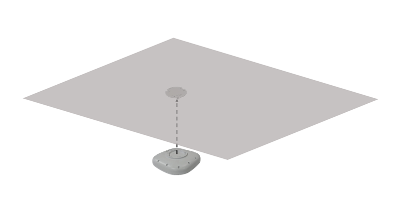 (3) Lift the anchor horizontally and align it with the chassis buckle | 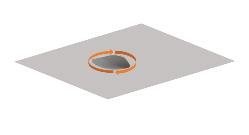 (4) After the anchor is inserted into the buckle, rotate it clockwise |
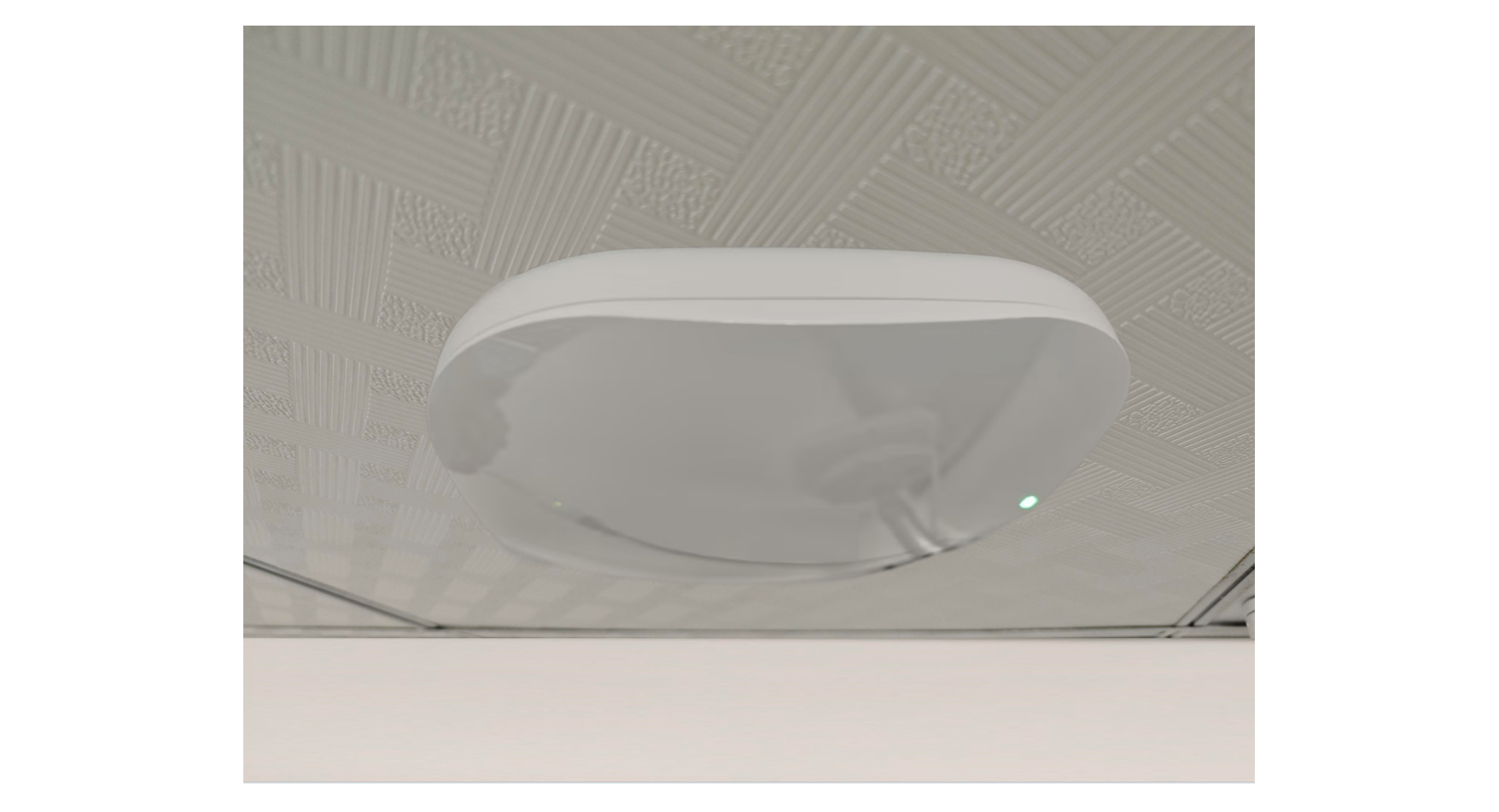 (5) Complete the anchor installation |  |
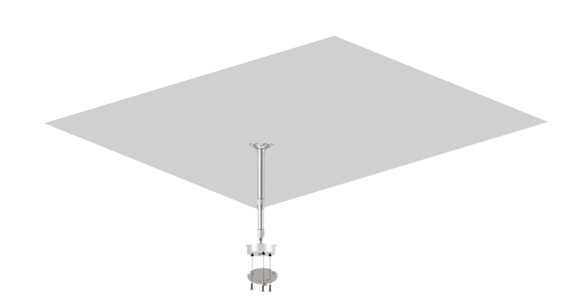
A02, A02M anchor-suspended rod installation
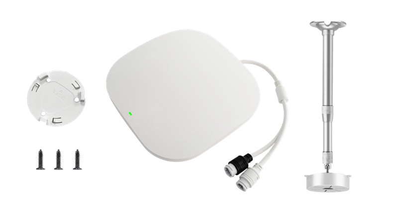 (1) Prepare the anchor, chassis, self-tapping screws and suspension rods | 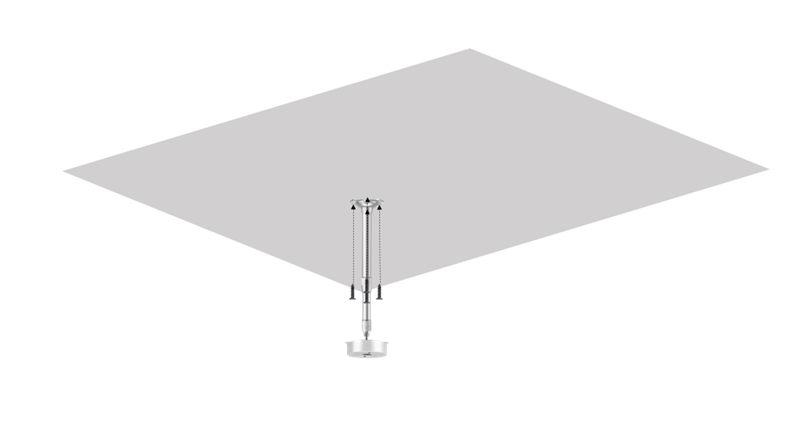 (2) Fix the suspension rod to the ceiling |
|---|---|
 (3) Fix the anchor chassis to the bottom of the boom | 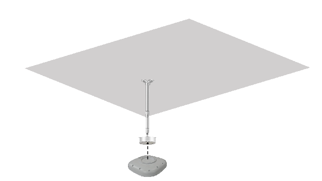 (4) Lift the anchor horizontally and align it with the chassis buckle |
 (5) After the anchor is inserted into the buckle, rotate it clockwise | 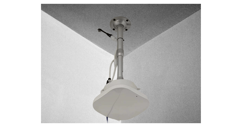 (5) Complete anchor installation |
A02P anchor - assembly
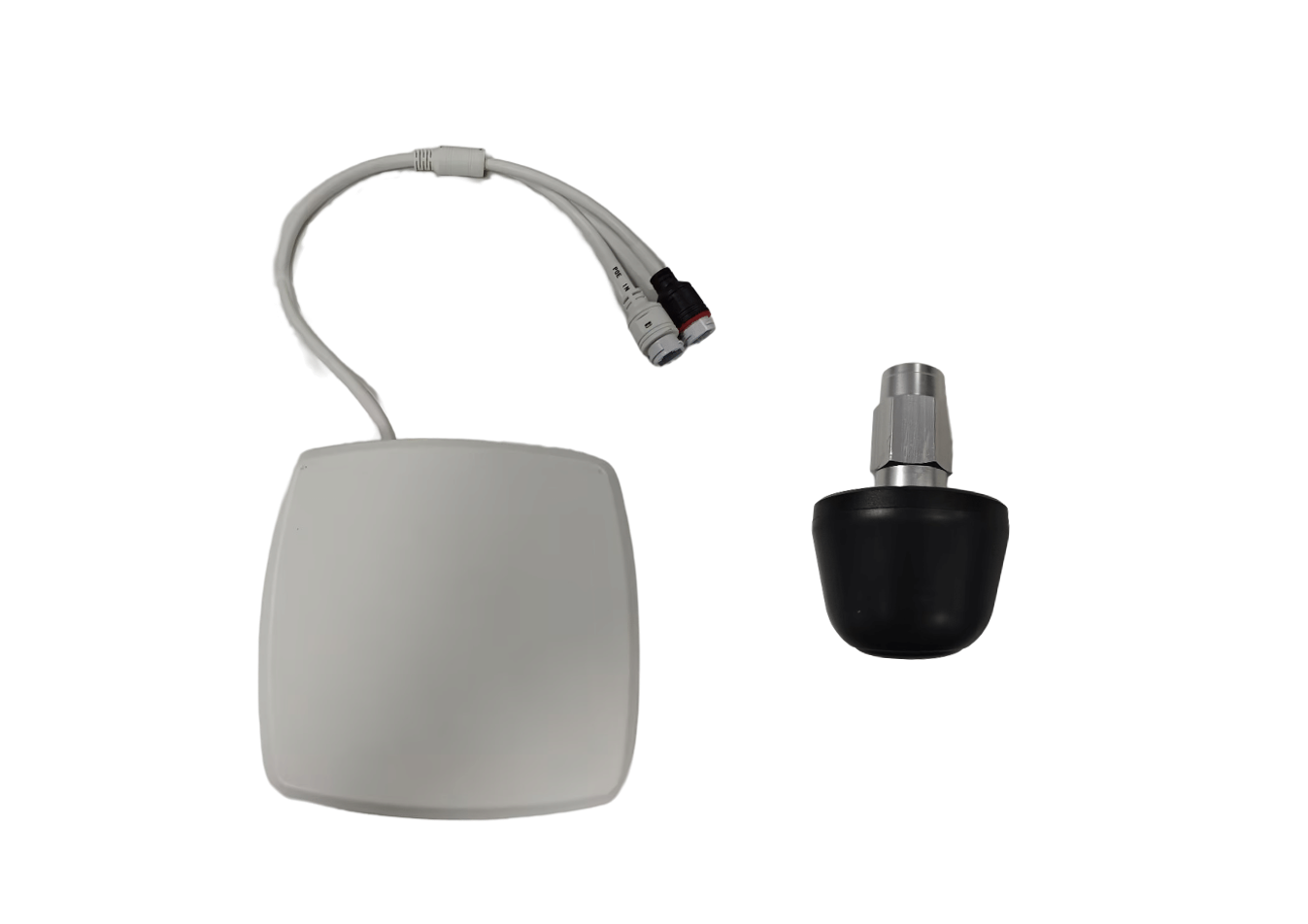 (1) Prepare anchor and antenna | 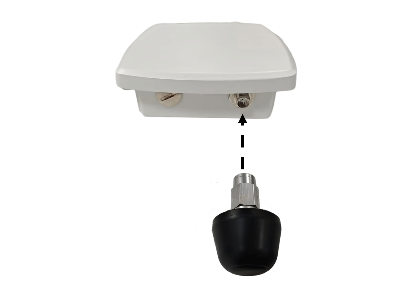 (2) Insert the antenna into the anchor antenna slot |
|---|---|
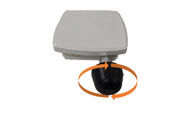 (3) Rotate the antenna clockwise until it is tightened | 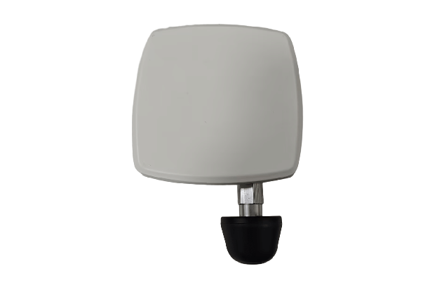 (4) Complete antenna installation |
A02P anchor - hoop installation
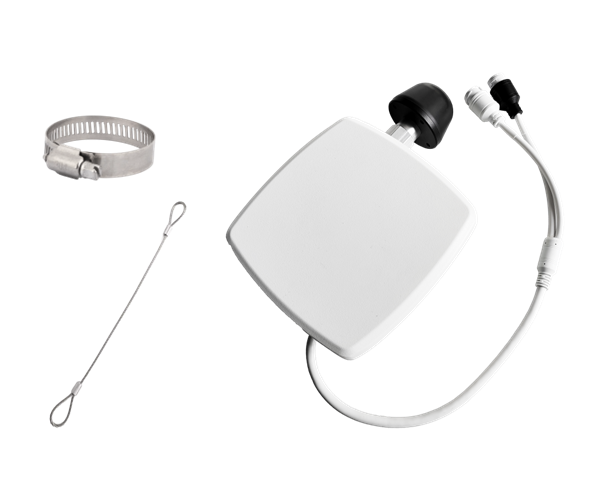 (1) Prepare anchor, hoop and safety rope | 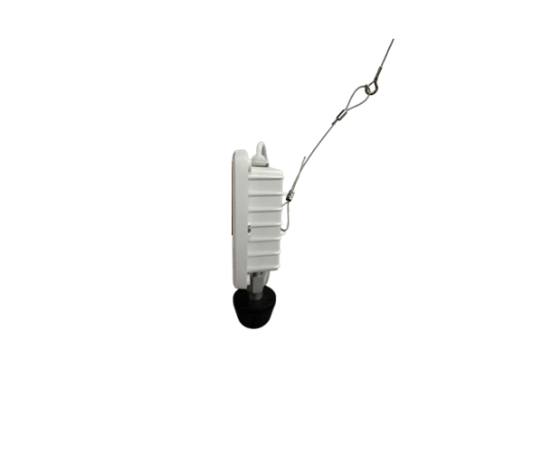 (2) One end of the safety rope is connected to the anchor, and the other end is fixed at a suitable position |
|---|---|
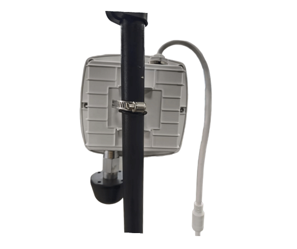 (3) Fix the anchor in a suitable position with a hoop | 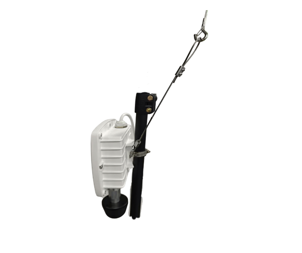 (4) Complete anchor installation |
A02P anchor antenna needs to face downwards
4. Anchor Installation Precautions
(1) Avoid occlusion
The anchor must be exposed, and there must be no obvious obstructions below or to the left or right of the anchor. Each positioning area must ensure that there is no obstruction between at least one anchor and the other anchor.
(2) Avoid metal reflection
The reflection of UWB signals by non-metallic materials has little effect on positioning, but if the reflecting surface contains metal materials, it will affect the positioning results.
Ceiling: The distance between the anchor and the ceiling is recommended to be greater than 30 cm, and it is recommended to use a support pole for installation.
Wall: It is recommended to install the anchor at least 20 cm away from the wall.
(4) Avoid interference
The anchor should be installed away from high-power wireless transmitters to avoid interference.
(5) Anchor deployment
Range: The installation range of a single anchor. For example, the maximum range of an A01 anchor at 6.5 GHz is 50 m*50 m.
Shape: The shape of the anchor directly determines the size of the geometric precision factor. It is generally recommended to install it in a square to maximize the average geometric precision factor. Take 4 anchors as the smallest positioning unit. When installed in a square with an aspect ratio of 1:1, the accuracy of the X and Y coordinates corresponding to the length and width is consistent; when installed in a rectangle with an aspect ratio of 2:1, the Y coordinate corresponding to the short side is nearly twice the difference of the X coordinate.
(6) Network configuration
For the same system, all anchors must be in the same network segment.
5. Switch Installation Considerations
(1) A switch equipped with a POE port must be used
(2) The switch should be installed in a clean, dry, well-ventilated, temperature-controlled place without strong electromagnetic interference. Avoid corrosive gases, water seepage, dripping, condensation, and avoid excessively high or low ambient temperatures that accelerate the aging of insulation materials.
6. Things to Note When Laying Network Cables
(1) Use Category 5e or higher network cables, and the length of a single network cable should not exceed 80 meters to maintain a stable connection
(2) Both ends of the network cable need to be marked accordingly to facilitate subsequent anchor deployment and maintenance
(3) It is recommended to leave about 1 to 2 meters of network cable when reserving
(4) When the on-site electromagnetic environment is complex or there is strong electrical interference, it is recommended to use shielded Category 5e or Category 6 network cables
(5) It is recommended to use a one-for-one backup method when laying network cables to improve the line's later fault tolerance capabilities
7. Network Cable Waterproof Connector Connection
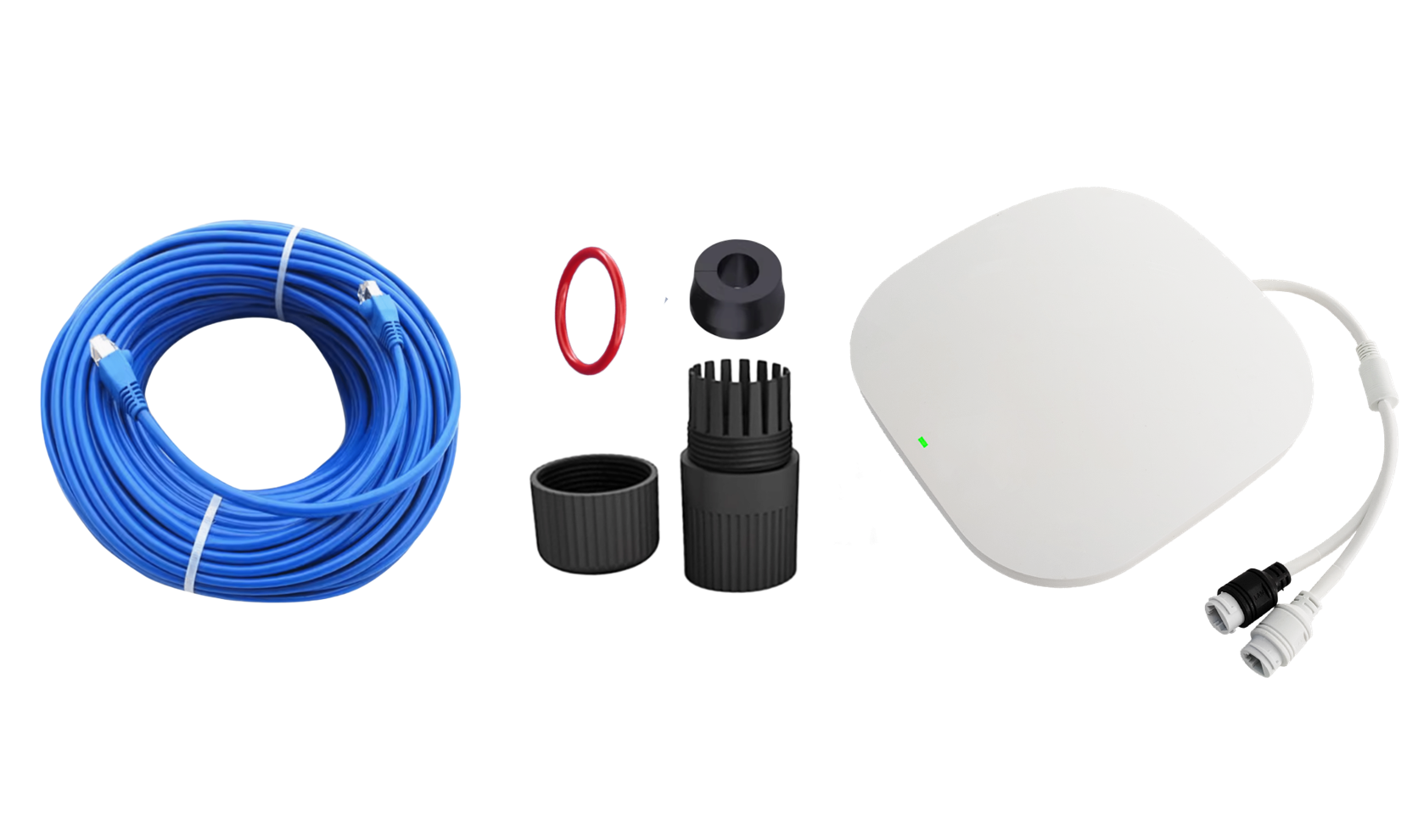 (1) Prepare anchor, network cable, and waterproof connector set | 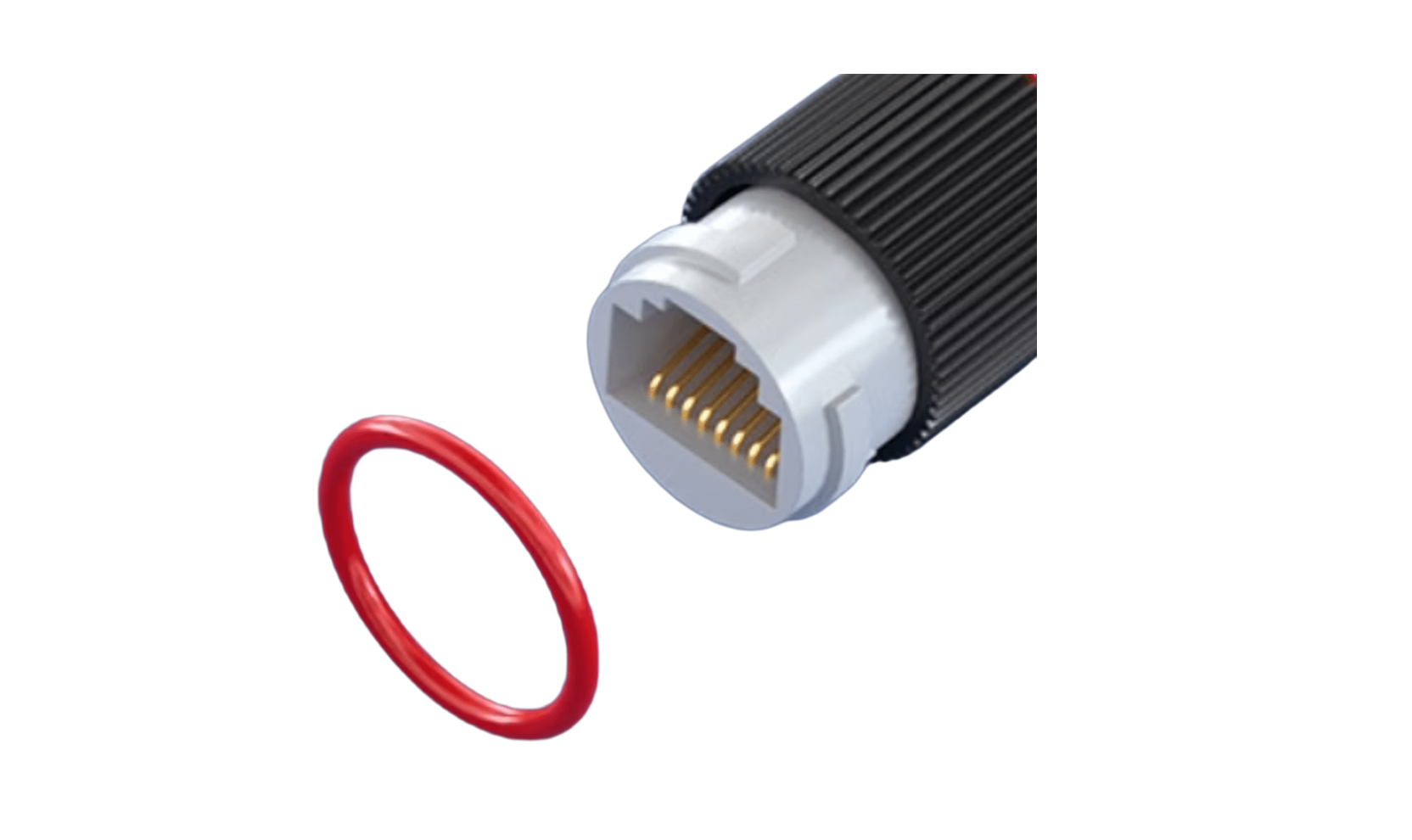 (2) Put the waterproof rubber ring into the anchor joint |
|---|---|
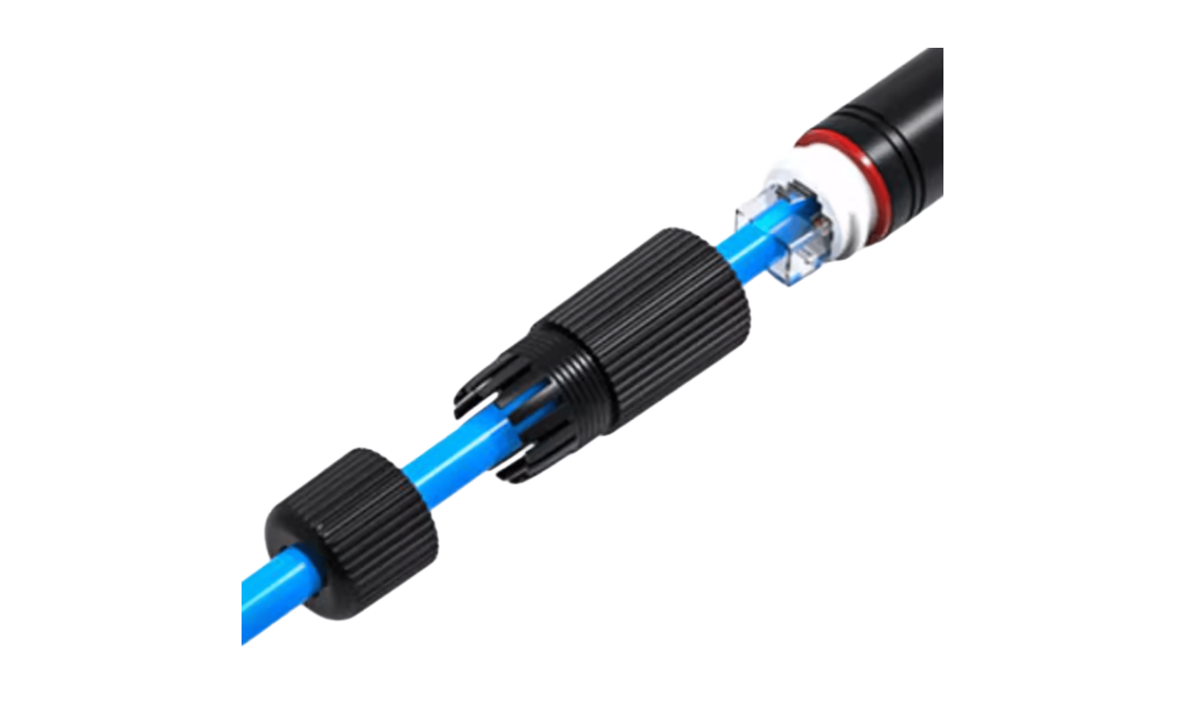 (3) Pass the network cable through the nut and insert the crystal head into the anchor interface | 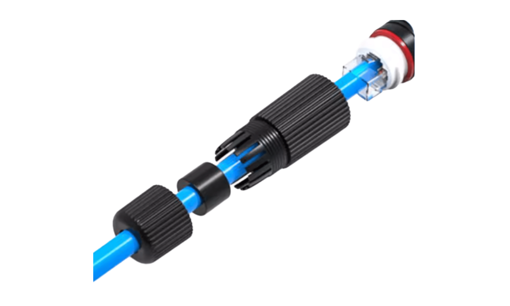 (4) Insert the waterproof rubber plug into the network cable and push it into the waterproof head |
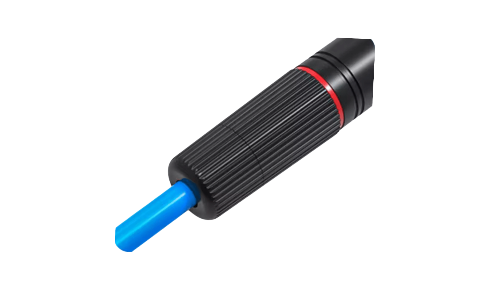 (5) Finally, tighten all parts | |
(1) The anchor in interface is connected to a switch or a cascaded upper device, and the anchor out interface is connected to a cascaded lower device or is not connected to any device.
(2) Some network cables cannot be put into the waterproof cover because the tail of the crystal head sheath is too large. It is necessary to remove the excess part or use a network cable with a bare crystal head.