Quick Start
Software Interface Overview
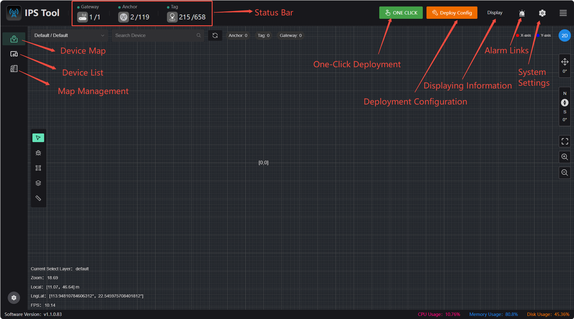
Detailed Explanation of Each Area's Functions
(1) Main Menu Bar: Contains the software’s commonly used functions and basic options. This area includes map upload, device list, and real-time location display.
(2) Advanced Settings Bar: Provides advanced configuration options for the software. This area includes base station tag status configuration, system login credentials, location display settings, alert display settings, and system and interface settings.
(3) Status Bar: Displays the software’s operational status and notification messages.
Anchor Deployment
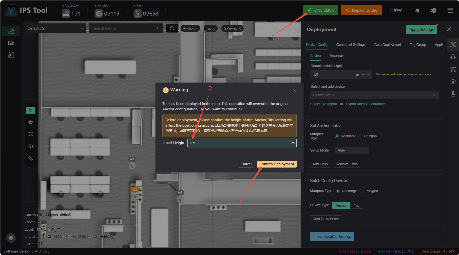
One-click deployment
Simply click the “One-Click Deployment (2–9 Anchors)” button. The configured height will match the actual installation height, and the deployment is expected to take about 1 minute. There are two important points to note regarding one-click deployment:
- One-Click Deployment automatically uses the anchor with the lowest UID as the origin, so the resulting anchor positions may not match the actual locations. If you need to ensure accurate alignment with the actual positions and orientations, you can use Auto Deployment or Manual Deployment to adjust them accordingly.
- One-Click Deployment is subject to uncertainty; obstructions during the process may cause deployment to fail. If you require high positioning accuracy, we recommend using Manual Deployment.
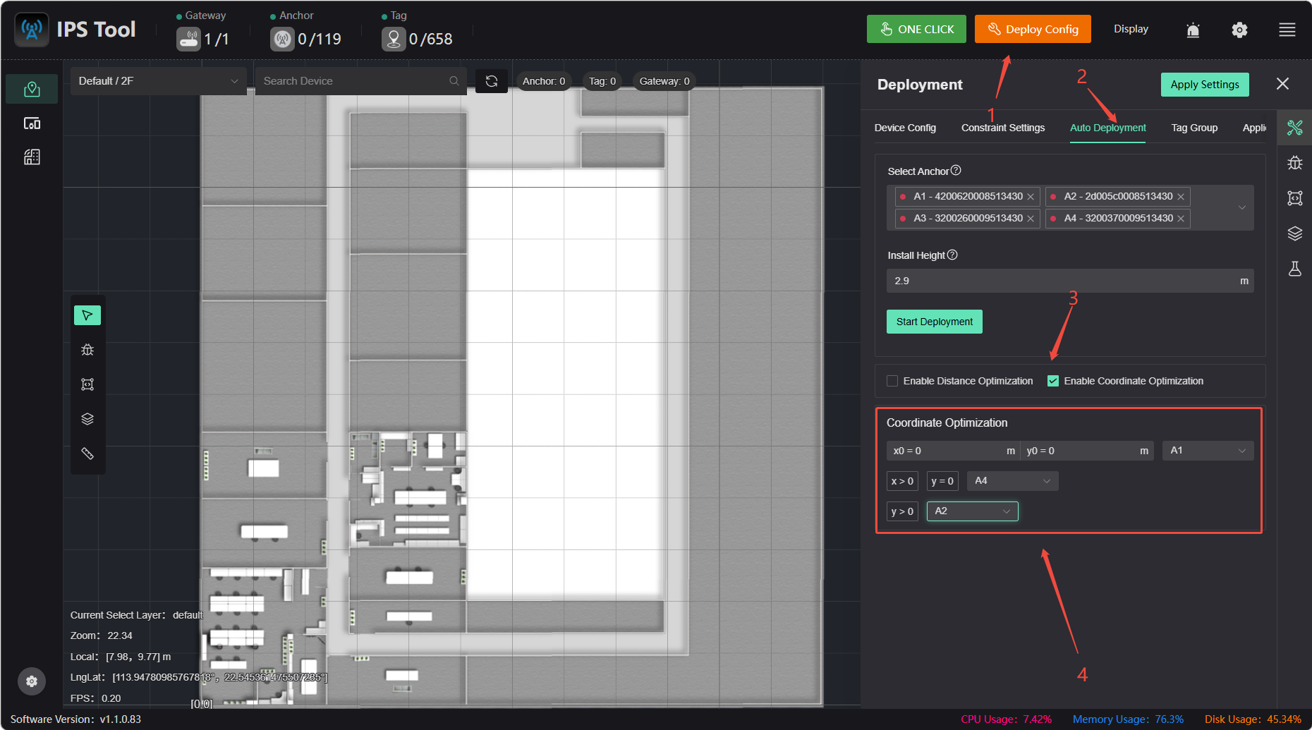
Automated deployment
Click “Automatic Deployment” in the deployment settings, select the anchor, enable coordinate optimization, and then click the “Start Deployment” button to complete the deployment.
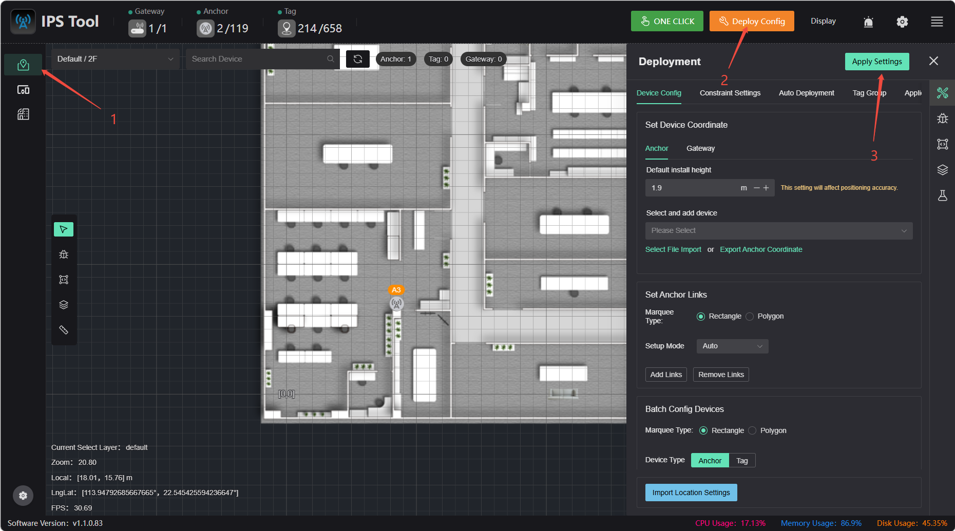
Manual Coordinate Deployment
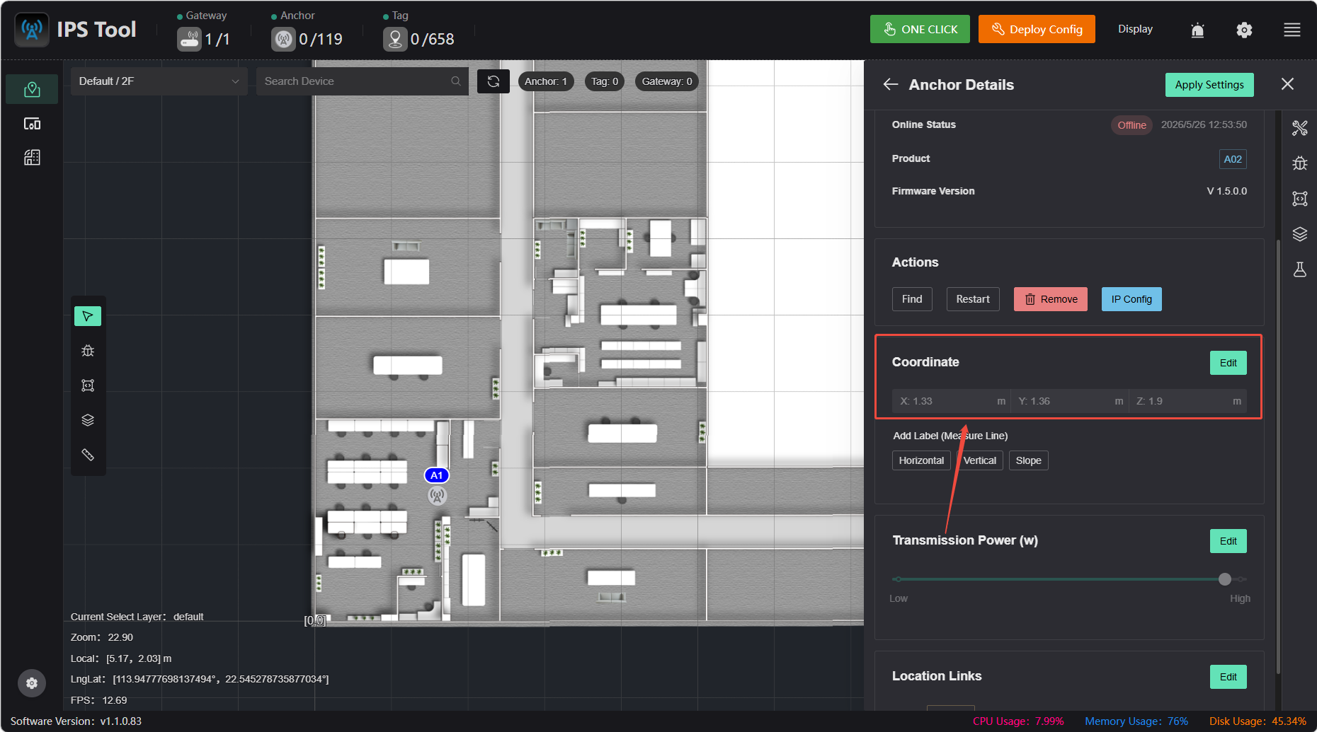
Click “Device Configuration” under “Deployment Configuration,” select “Add Device,” and tap on the map to add it. Tap an anchor on the map to edit its coordinates.
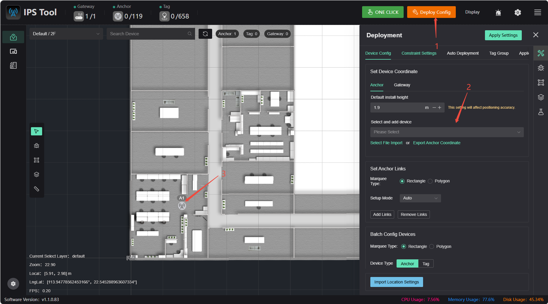
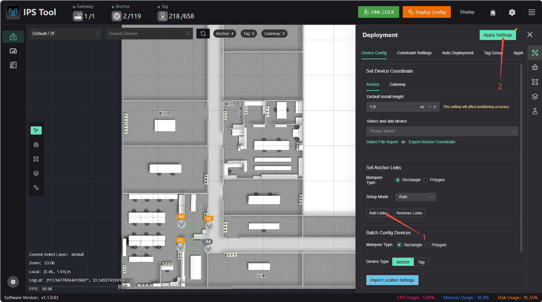
After editing the coordinates, select the area to add the link, then click “Apply Settings” to complete the manual deployment. The link is for informational purposes only and does not affect positioning accuracy.
Coordinate Measurement Methods
Meaning of Anchor Coordinates: The x and y coordinates of an anchor represent the horizontal and vertical distances, respectively, from the anchor’s position to the map origin (0,0).
Case A: The Origin is Directly Measurable
If the anchor has a direct line of sight to the map origin, simply use a tape measure or rangefinder to measure the distances from the anchor to the origin in the x and y directions; these two values are the anchor’s coordinates.
Scenario B: When Direct Measurement to the Origin Is Not Feasible (Reference Point Method)
⚠️ Prerequisites: The map has been imported and configured correctly; ensure that the map coordinates of the reference point match its actual location.
When the site is large, the origin is obstructed, or direct measurement is impractical, you can select a reference object with known coordinates (such as a wall corner or pillar). By measuring the anchor’s offset relative to the reference object, the software will automatically calculate the coordinates.
Procedure:
- Identify a reference point on the map.
- On-site, use a tape measure or measuring device to measure the horizontal and vertical distances from the anchor to the reference point.
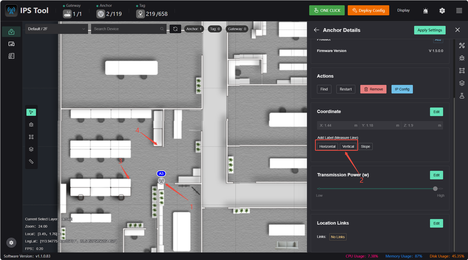
- Return to the software, select the anchor, and use the “Auxiliary Measurement Line” feature:
- Click the “Horizontal” or “Vertical” button, then click the reference point to automatically generate an auxiliary measurement line.
- Enter the horizontal and vertical distances measured in Step 2 into the input fields (enter absolute values; the software will automatically determine the positive or negative sign based on the direction of the measurement lines).
- After entering the values, the software will automatically calculate the anchor coordinates.
- Measure the anchor installation height (Z) directly using a distance measuring device.
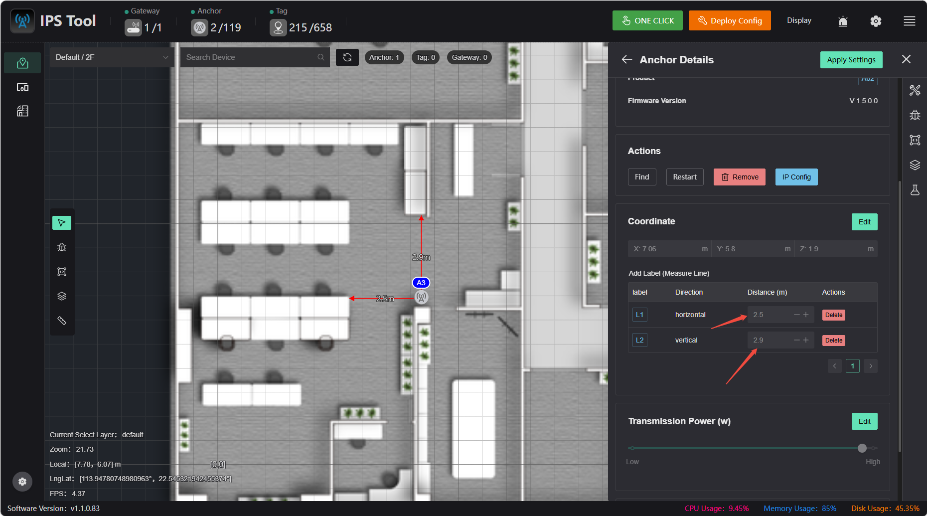
Example (see figure below):
- Using the corner of the desk as a reference point, measure the distance from the anchor to the left corner of the desk as 2.5 m and the distance to the top corner of the desk as 2.9 m using a tape measure or distance meter.
- In the software, enter
2.5for the horizontal distance and2.9for the vertical distance. - Once entered, the anchor coordinates are automatically calculated.
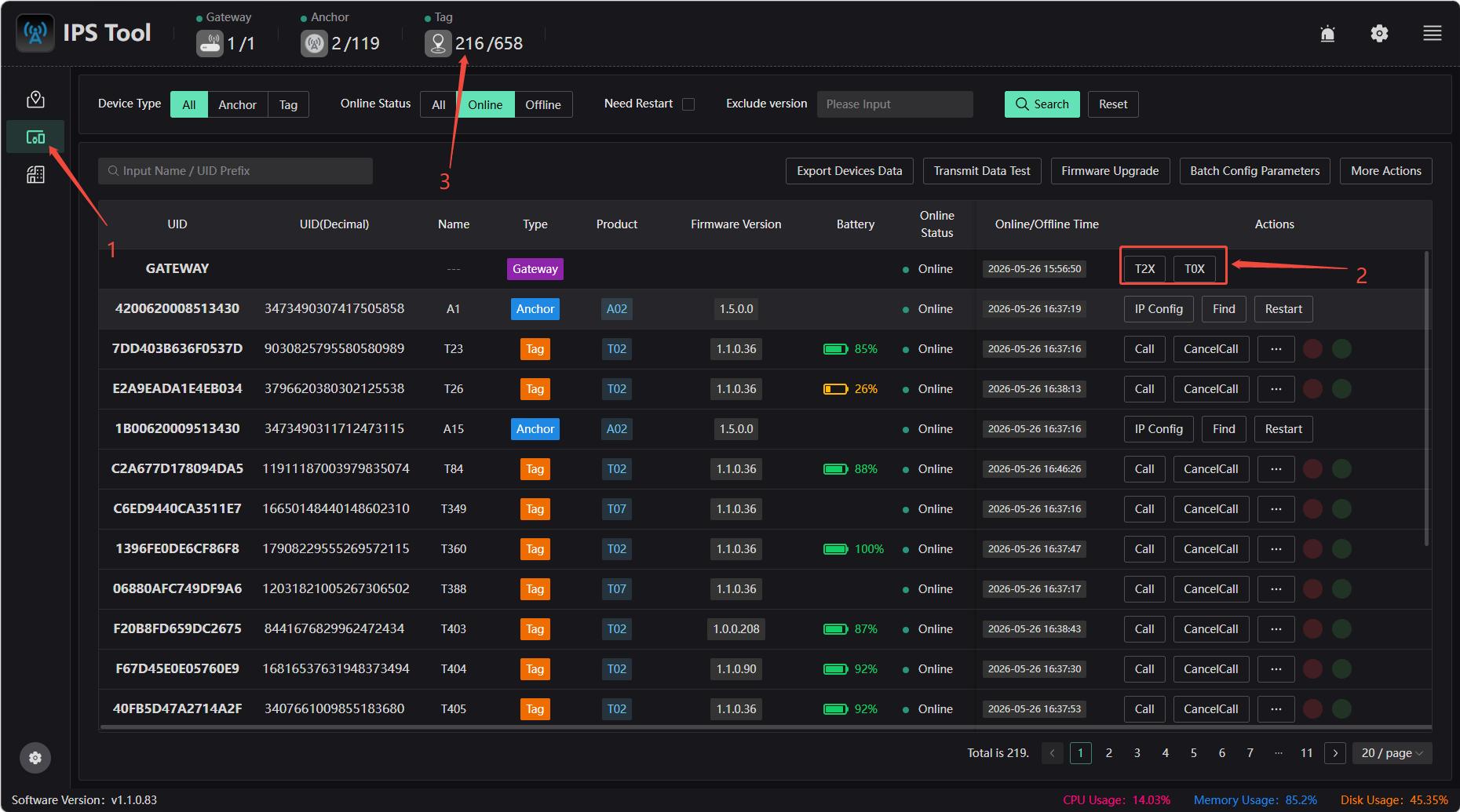
Tags are now live
After the Anchor is deployed, press and hold the tag’s power button for 3 seconds. When the indicator light flashes, the tag is powered on and ready for use.
⚠️ Important Note
- Currently, tags are divided into two types: T0X and T2X. They operate on different frequency bands, and the gateway and tag must be on the same frequency band to communicate properly.
Configuring the Frequency Band:
- Go to the device details page and tap the corresponding tag frequency band.
- Return to the main page and tap “App Settings” to apply the configuration.