Using Software Features
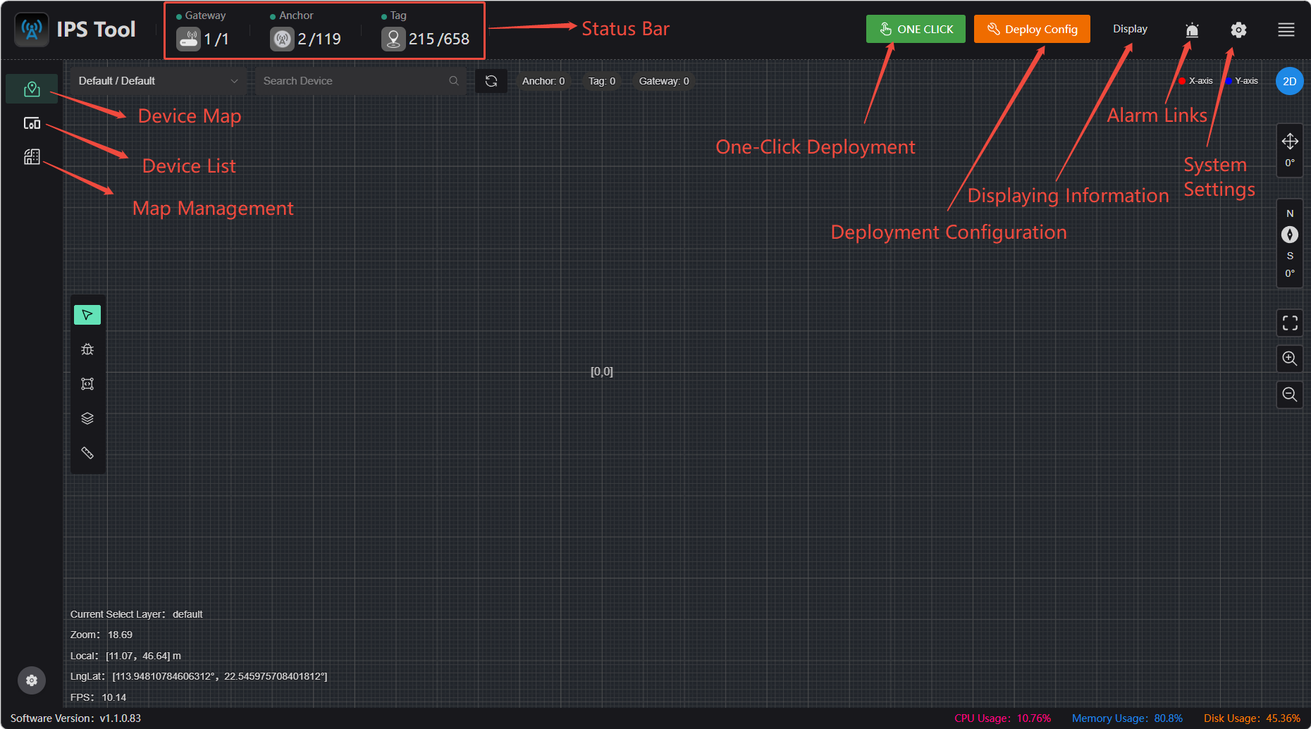
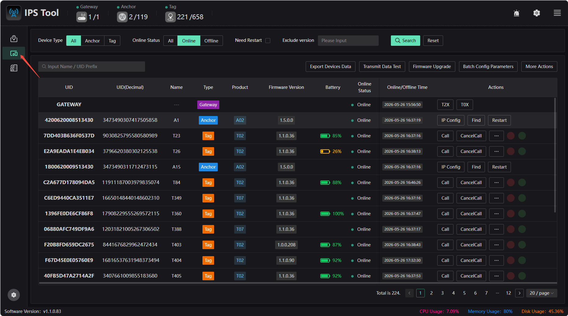
Equipment List
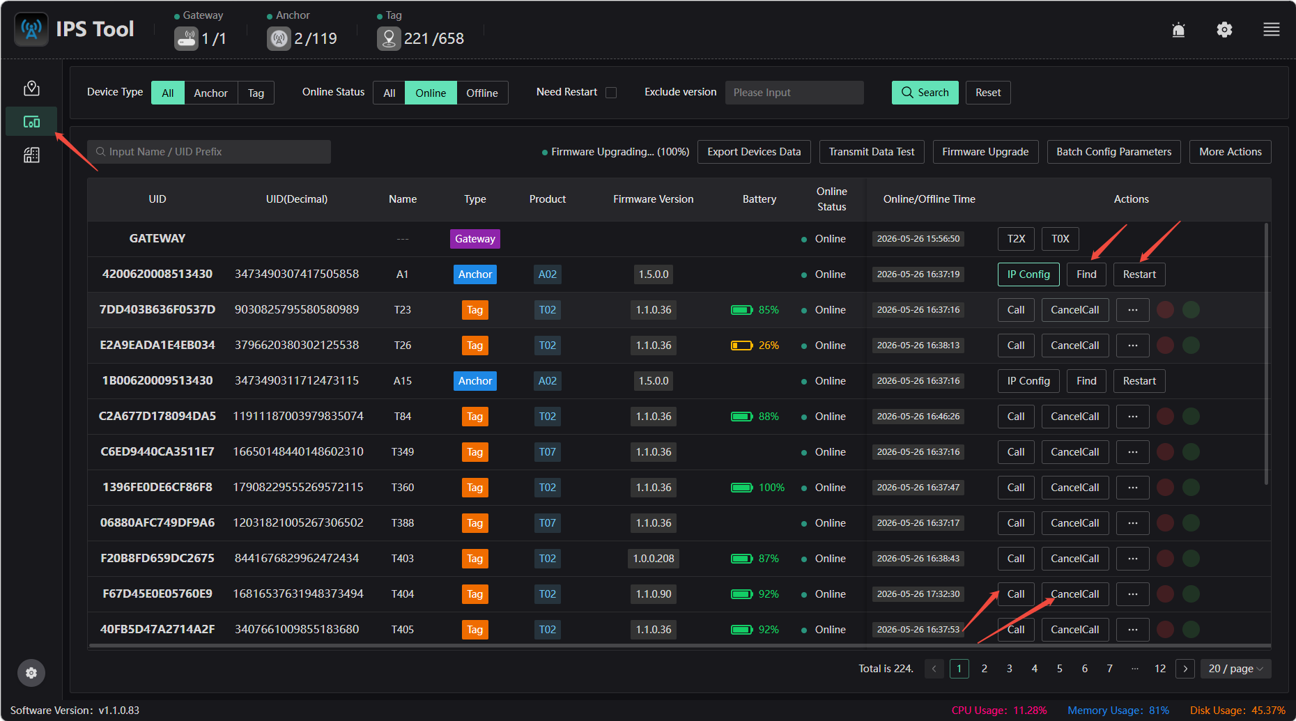
Click “Device List” on the left to view devices, check for firmware updates, configure parameters in bulk, view device details, and more.
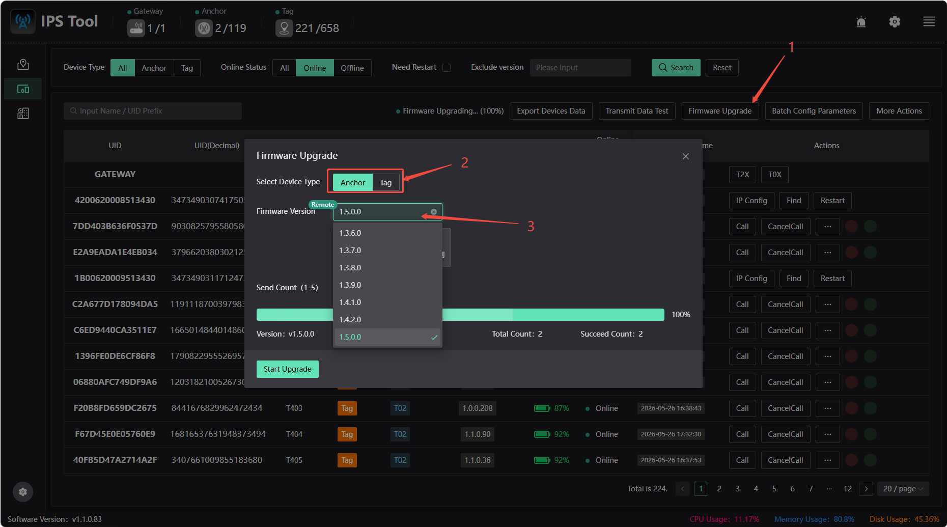
Firmware Update
Click the Firmware Update button to update the firmware for the base station and tags. Note: Please contact the official support team for confirmation before updating.
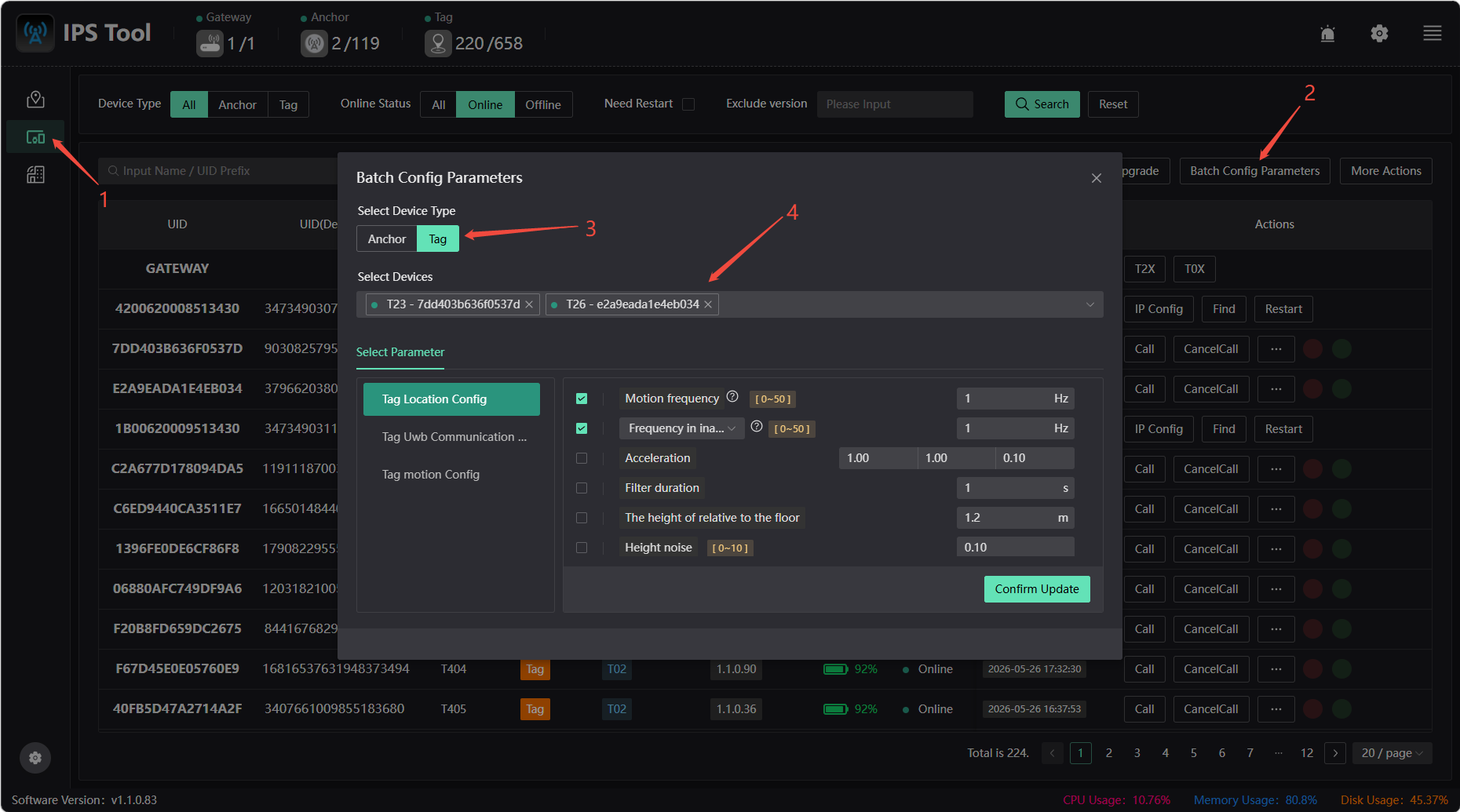
Batch configuration parameters
You can configure parameters for launch anchors and tags in bulk or specify them individually.
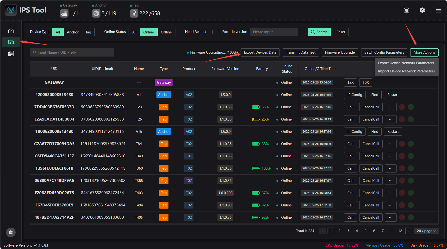
Export device information
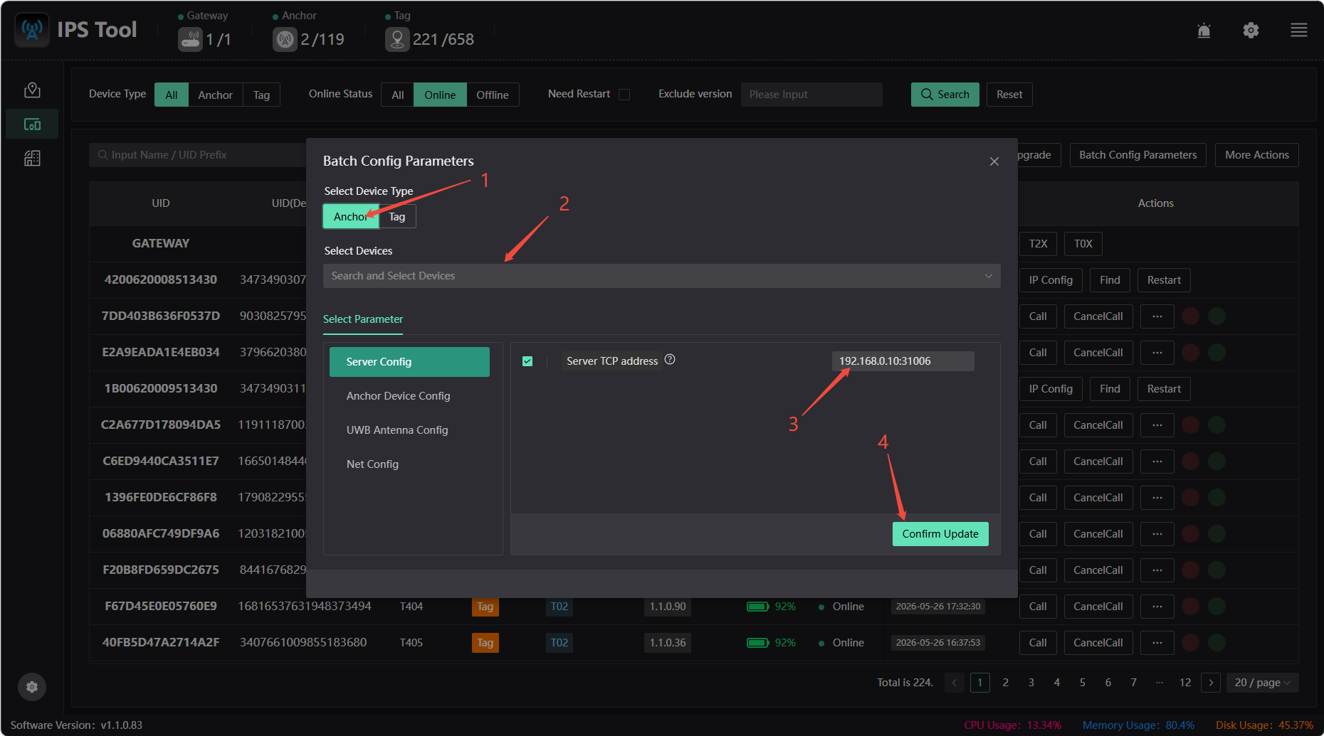
Configuring the Anchor Target IP
To change the Anchor target server IP (ensure network connectivity): Enter the new server IP address in the “Server TCP Address” field (leave port 31006 unchanged), click [Confirm Update], then restart the Anchor device, and finally change your computer's IP address. Note: The default reporting address for Anchor is xxx.xxx.xxx.254
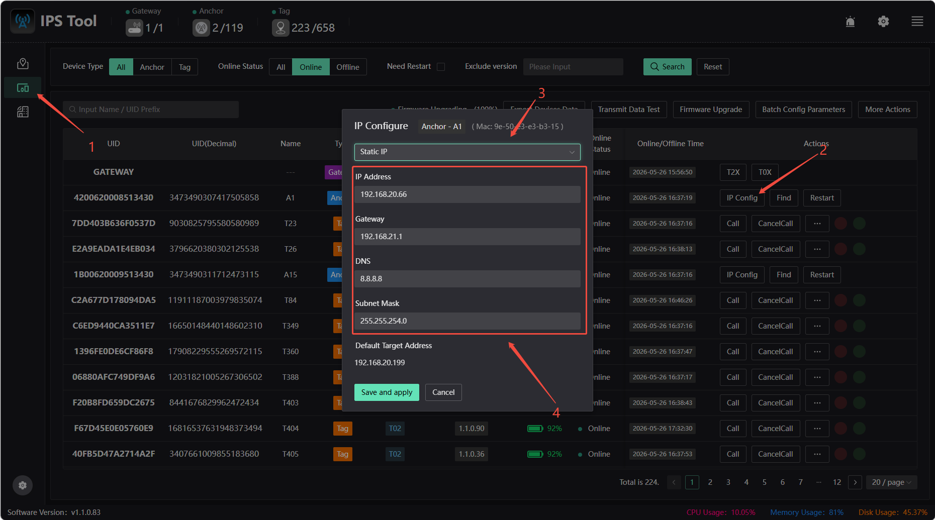
Configuring a Static IP for Anchor
By default, IP addresses are assigned via DHCP, but you can also assign a static IP. Follow these steps:
- Configure a static IP in the device list
- Click on Anchor on the map to configure a static IP
Locate, restart devices, etc.
- Device List Operations
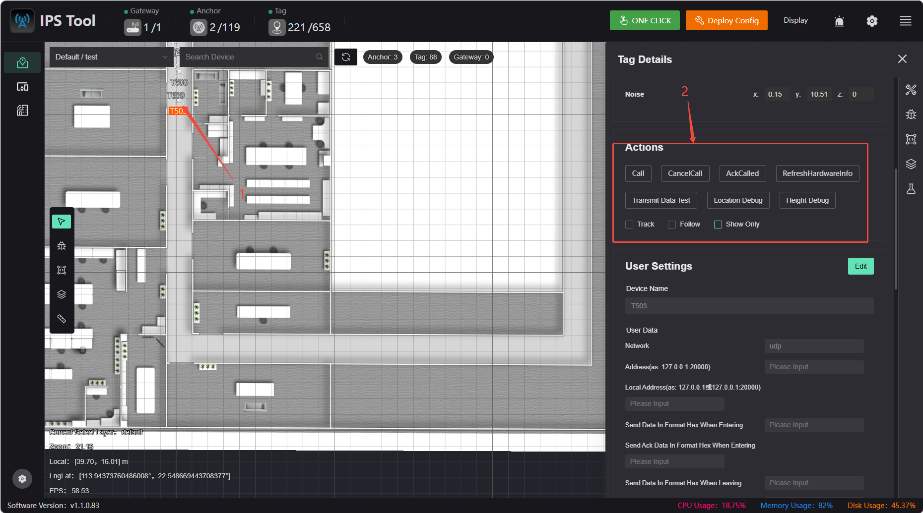
- Device Operations on the Map
Find: Clicking Find causes the corresponding beacon to flash, making it easier to locate the specified beacon.
Restart: Click the Restart button to restart the beacon.
Call: Sends a call command to the selected tag. The tag will flash to alert the user, making it easier to locate the physical device.
Cancel Call: Sends a command to cancel the call to the tag. The tag stops flashing.
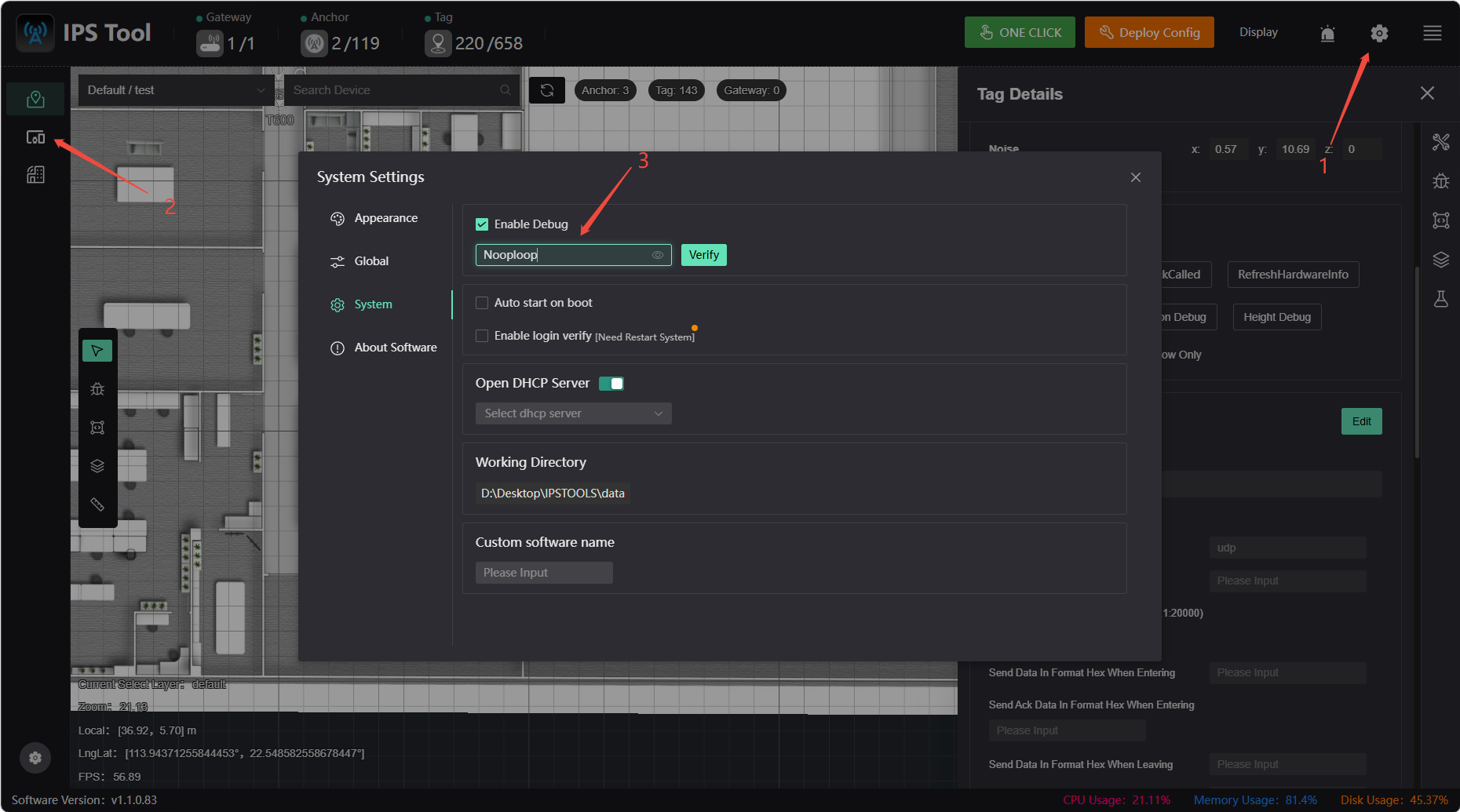
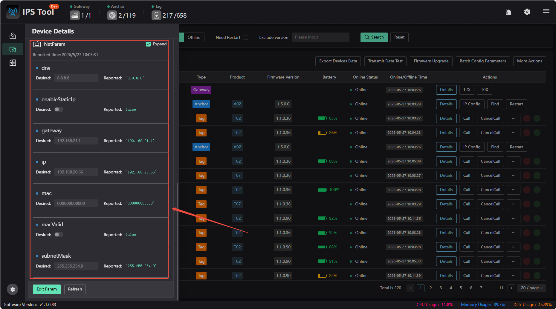
Device Details
To view device details, first click “Settings,” enable debugging, and enter the password “Nooploop.” You can then view detailed information about the gateway, anchor, and tags.
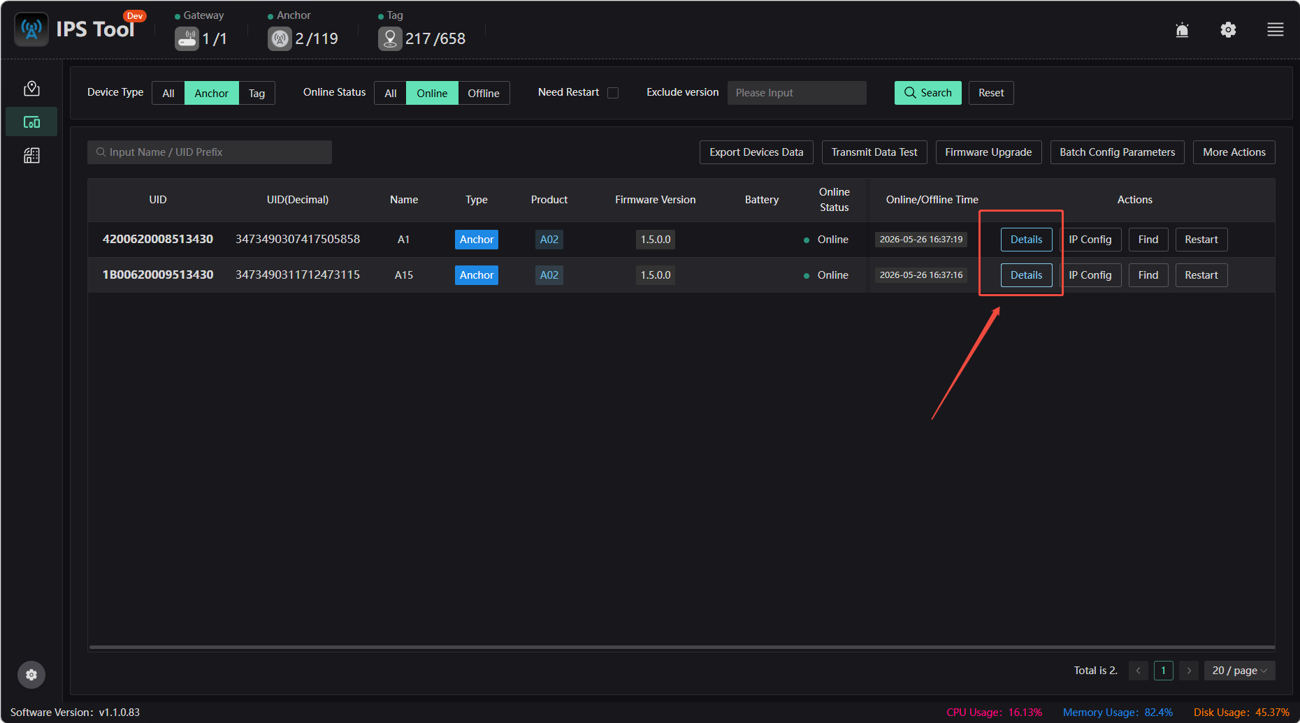
View the IP address of the server the anchor actually points to
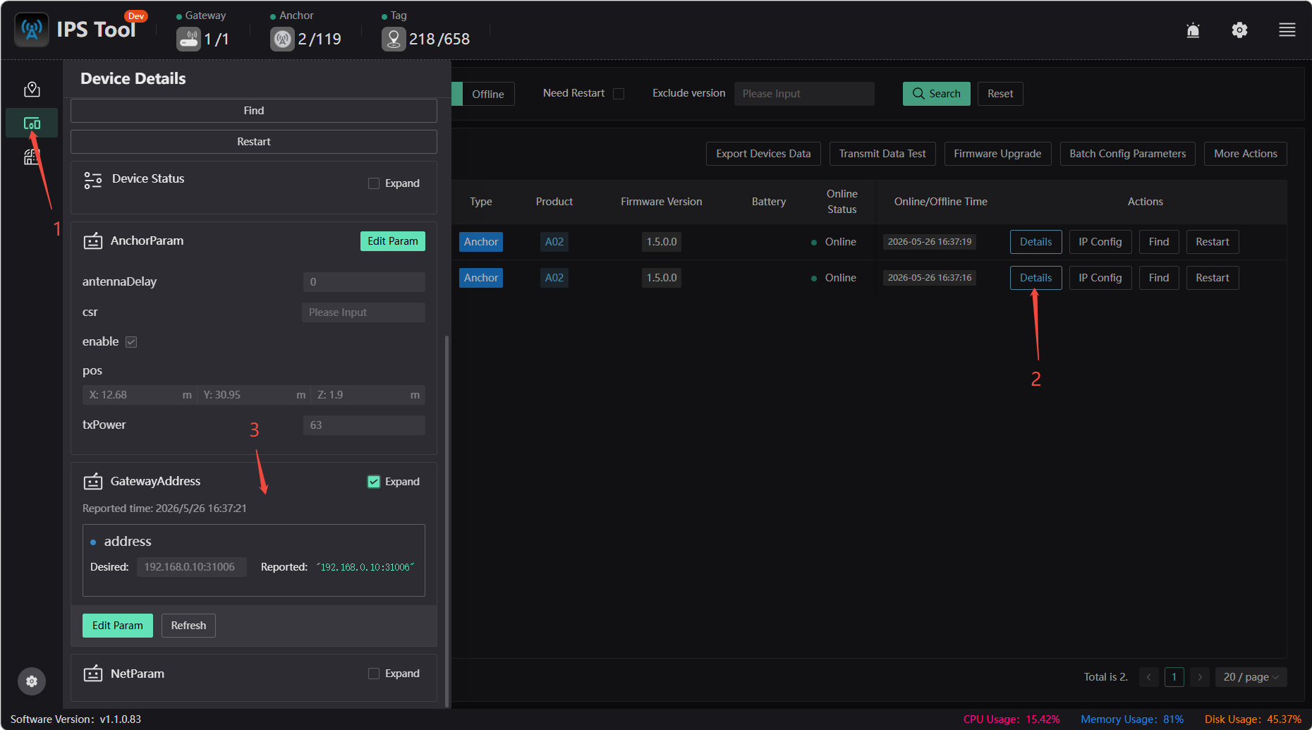
View the static IP address, gateway address, and other information for the anchor
Constraint Settings
By default, the map includes a plane constraint that limits the label height to the desired height. You can also choose to add several other types of constraint areas. Constraint areas are independent of positioning areas; simply add them where needed. The range of a constraint area defines the scope within which the constraint takes effect; the constraint only applies when the label’s coordinates fall within that range. Therefore, you should adjust the range based on your specific circumstances and requirements.
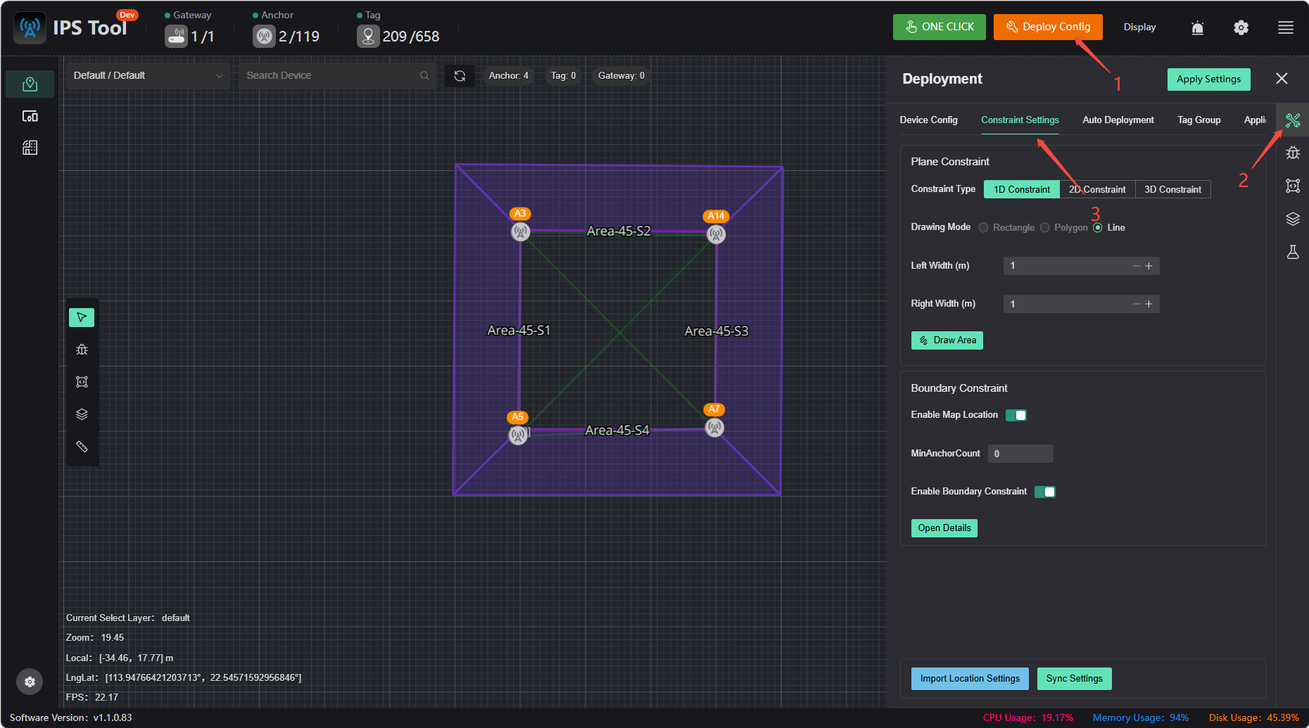
One-Dimensional Constraints
These are typically used in one-dimensional regions. Due to the underdetermined nature of one-dimensional regions, constraints must be added; otherwise, there will be no unique solution. One-dimensional constraints can also be added when drift in localization is observed at certain locations due to occlusion, to restrict the localization results to the desired positions (e.g., by adding constraints at the boundaries of the region to prevent the localization results from drifting outside the region).
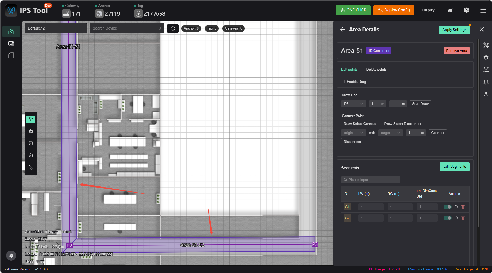
The constraint standard deviation indicates the strength of the constraint; the smaller the standard deviation, the stronger the constraint and the greater the adhesive force. If the constraint is too strong, it may prevent the object from leaving the constraint area from the side or cause significant delay in leaving it. The standard deviation is typically set to half the width.
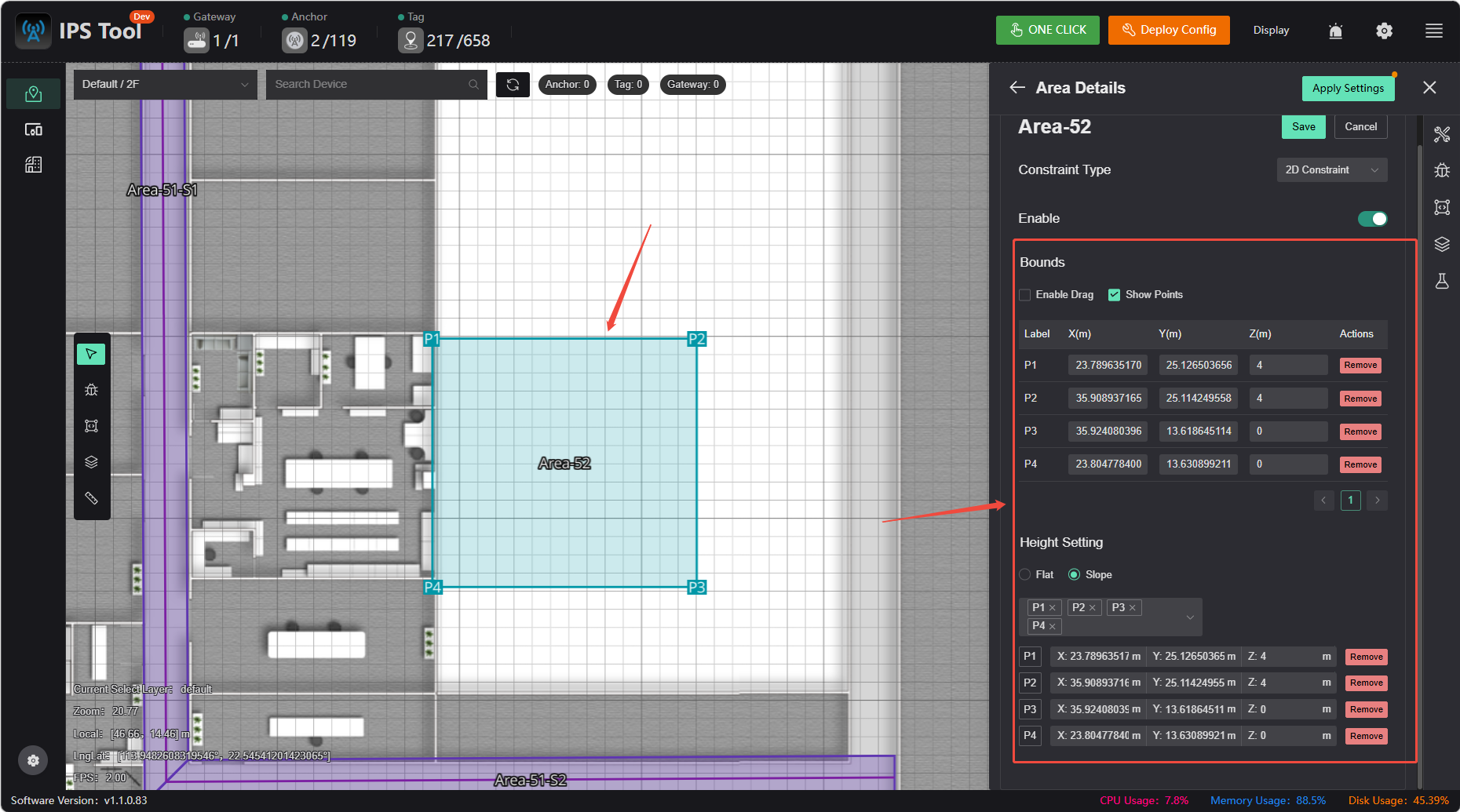
2D Constraints
If a particular area contains platforms or slopes at elevations different from the map's zero plane (and with significant elevation differences), it is necessary to create surface constraints to simulate these platforms or slopes. This ensures that when labels are moved to the corresponding positions, their elevations adjust accordingly, thereby improving XY accuracy.
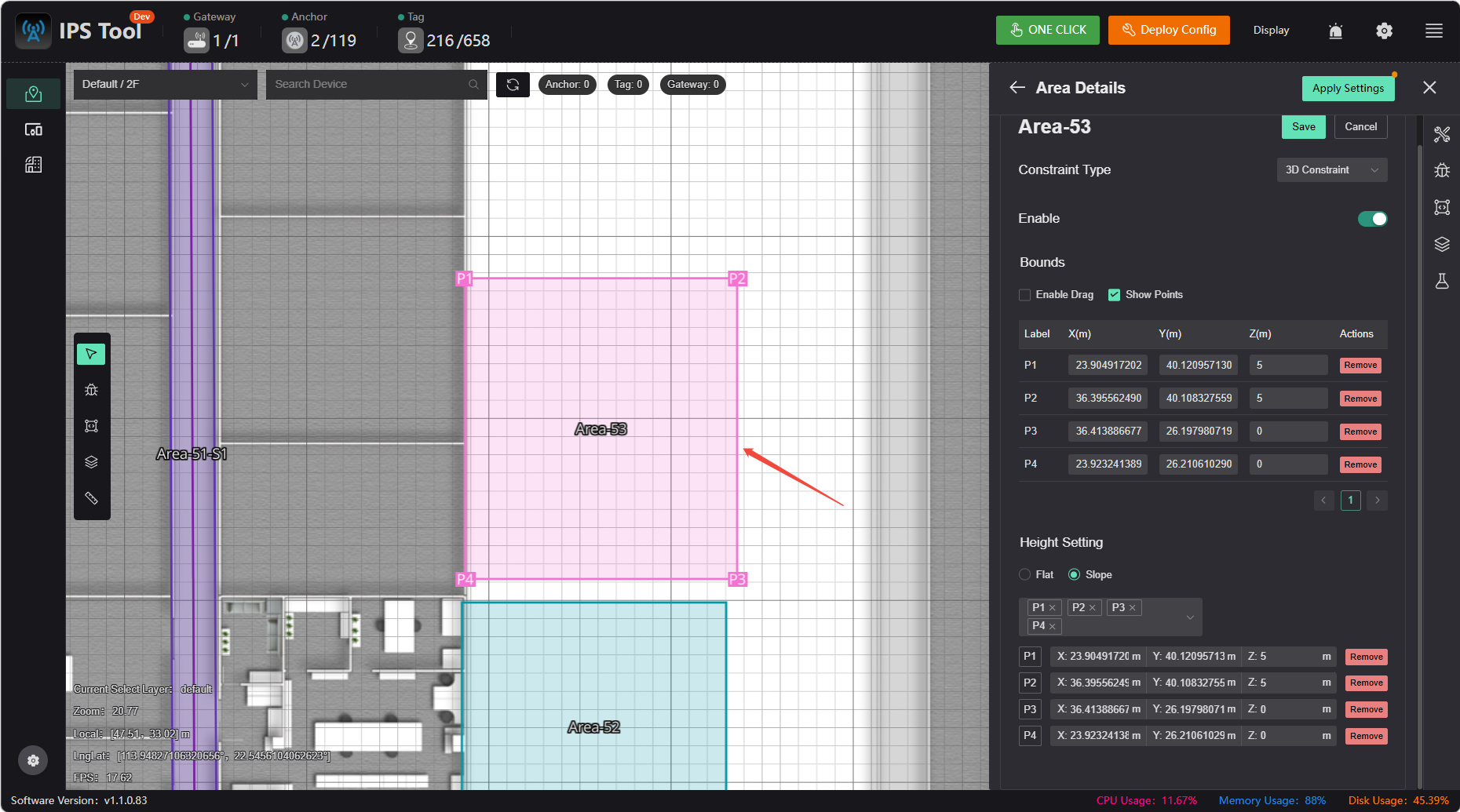
3D Constraints
This method is rarely used and is only necessary in areas where precise 3D coordinates are required. However, additional anchors must be added in the corresponding areas, and the height difference in the Z-axis should be similar to that in the X and Y axes. For example, if a 5×5 room requires 3D positioning, the recommended deployment method is to place four sensors on the ceiling and four on the floor, and configure 3D constraints.
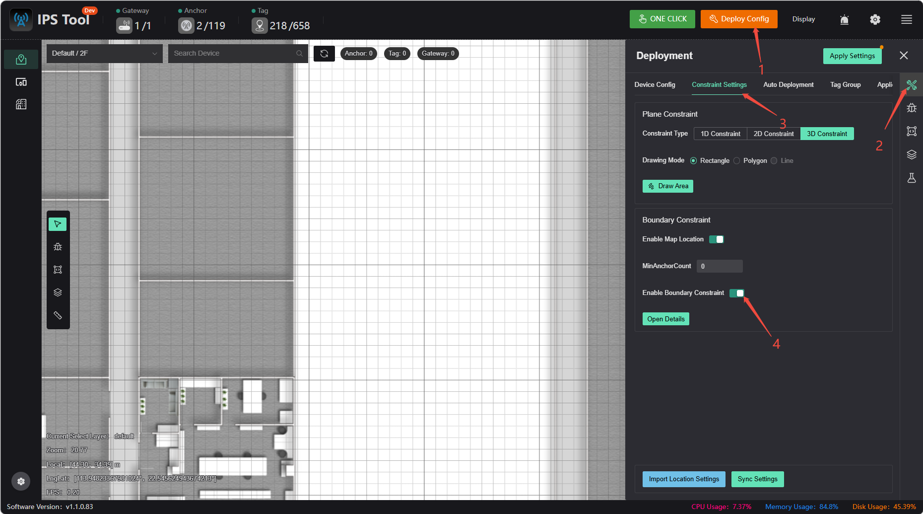
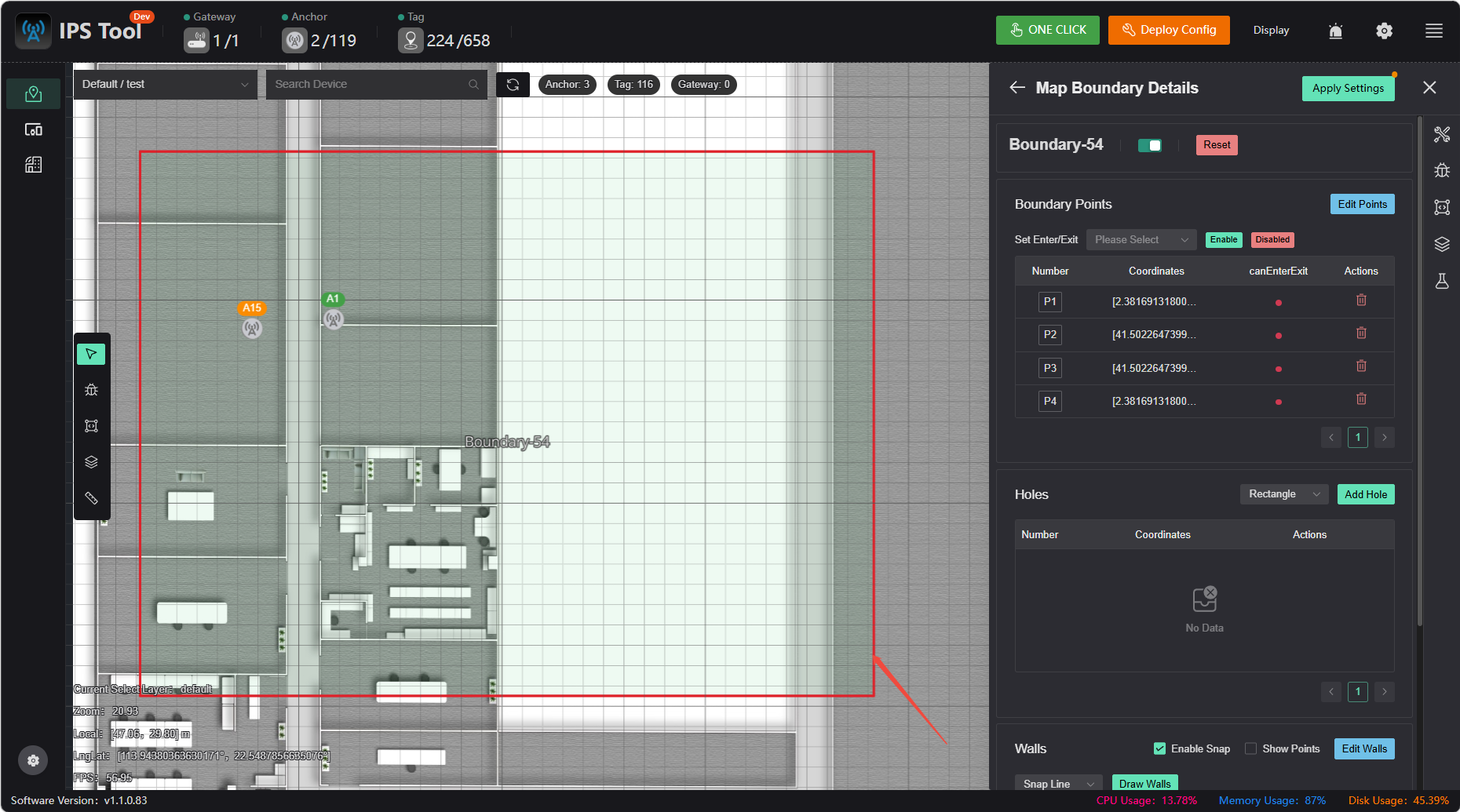
Boundary Constraints
Based on the actual physical environment, one or more closed areas can be predefined on the map. The system uses these areas as the valid positioning range and intelligently corrects the real-time coordinates returned by the tags to ensure they are always displayed within a reasonable spatial range
- Effectively suppresses non-line-of-sight errors caused by signal reflection, obstruction, and other factors, preventing tag positions from appearing in unreasonable areas outside of obstacles such as walls and partitions (i.e., the “wall-penetration” phenomenon), thereby enhancing the physical credibility of the positioning trajectory.
- When positioning signals experience brief fluctuations or partial loss of anchor signals, this feature constrains the tag’s position within known valid areas, preventing significant and meaningless drifts in position data and ensuring positioning continuity.
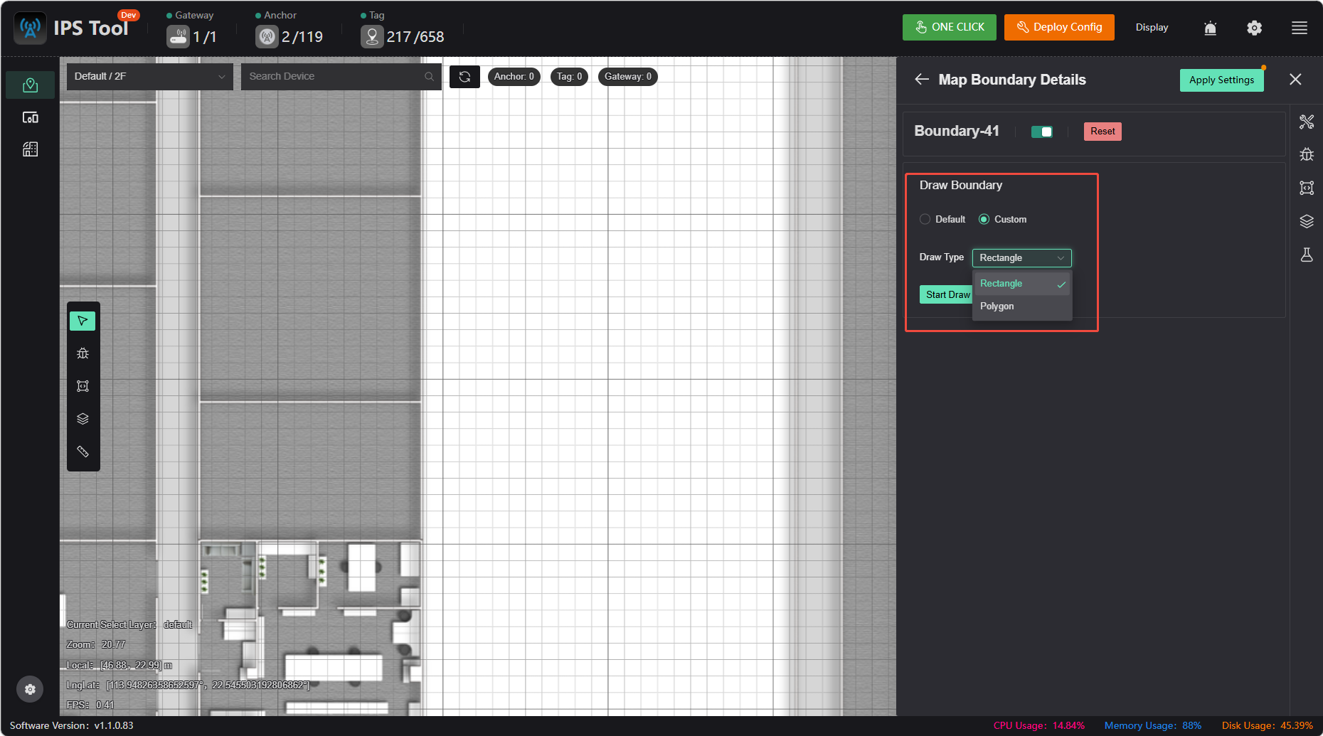
1.Click to enable boundary constraints
2.Click “Custom” to select a drawing method and draw the boundary
Additional Features
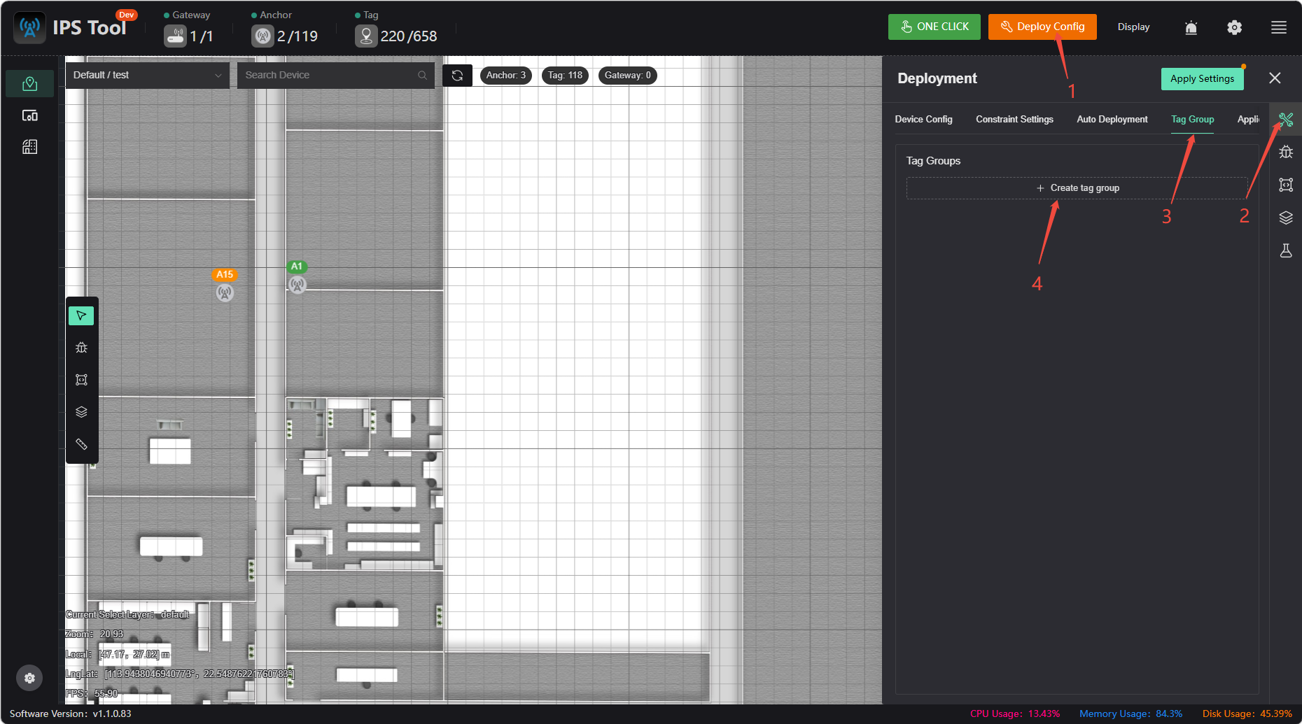
Combined Tag Localization
In cases of obstructions or environments with multipath interference (caused by large metal or glass surfaces, for example), combined positioning can be used to mitigate these effects and optimize positioning accuracy.
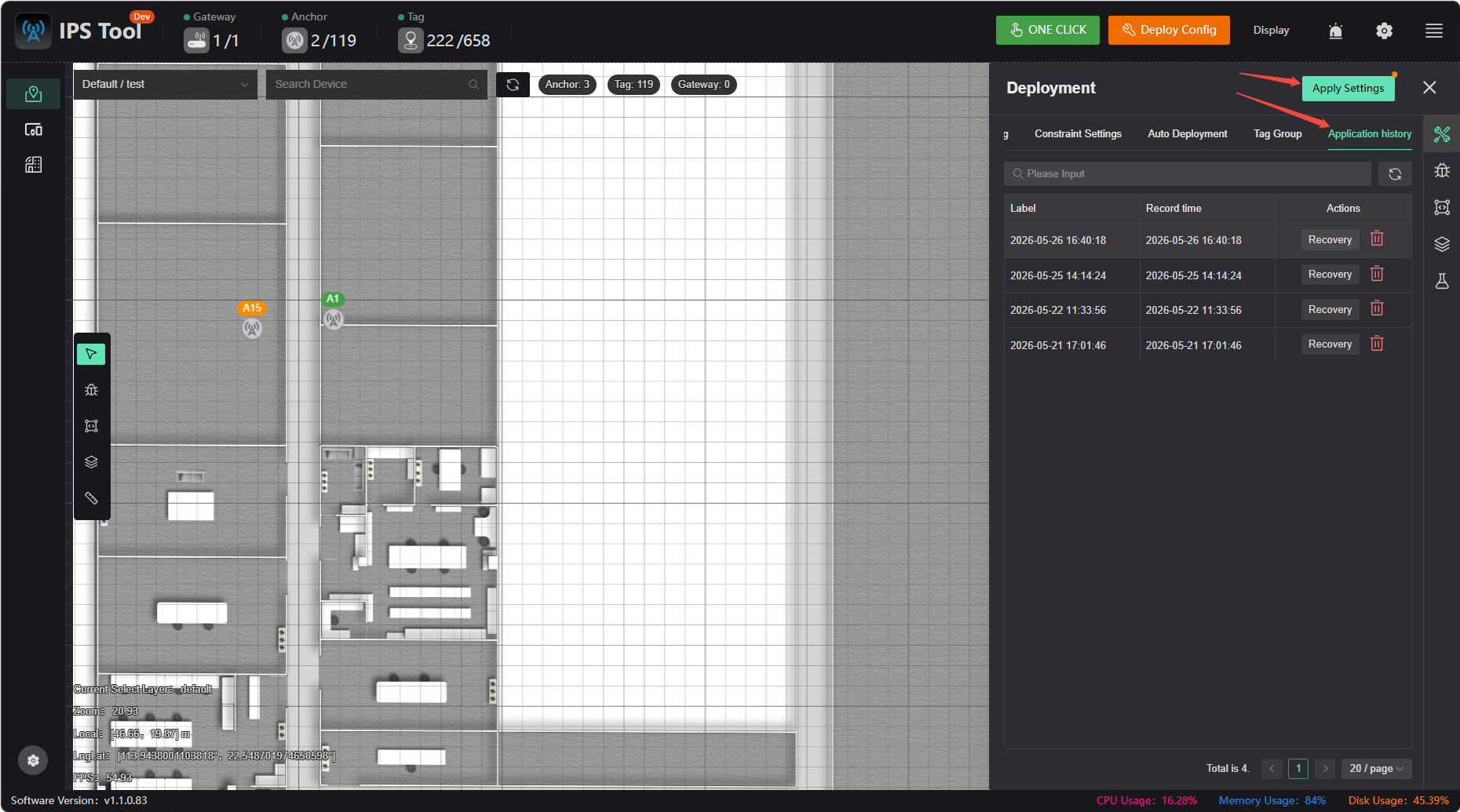
App History
If you've made a mistake, you can undo it in the App History. Clicking the App Settings button creates an entry in the history.
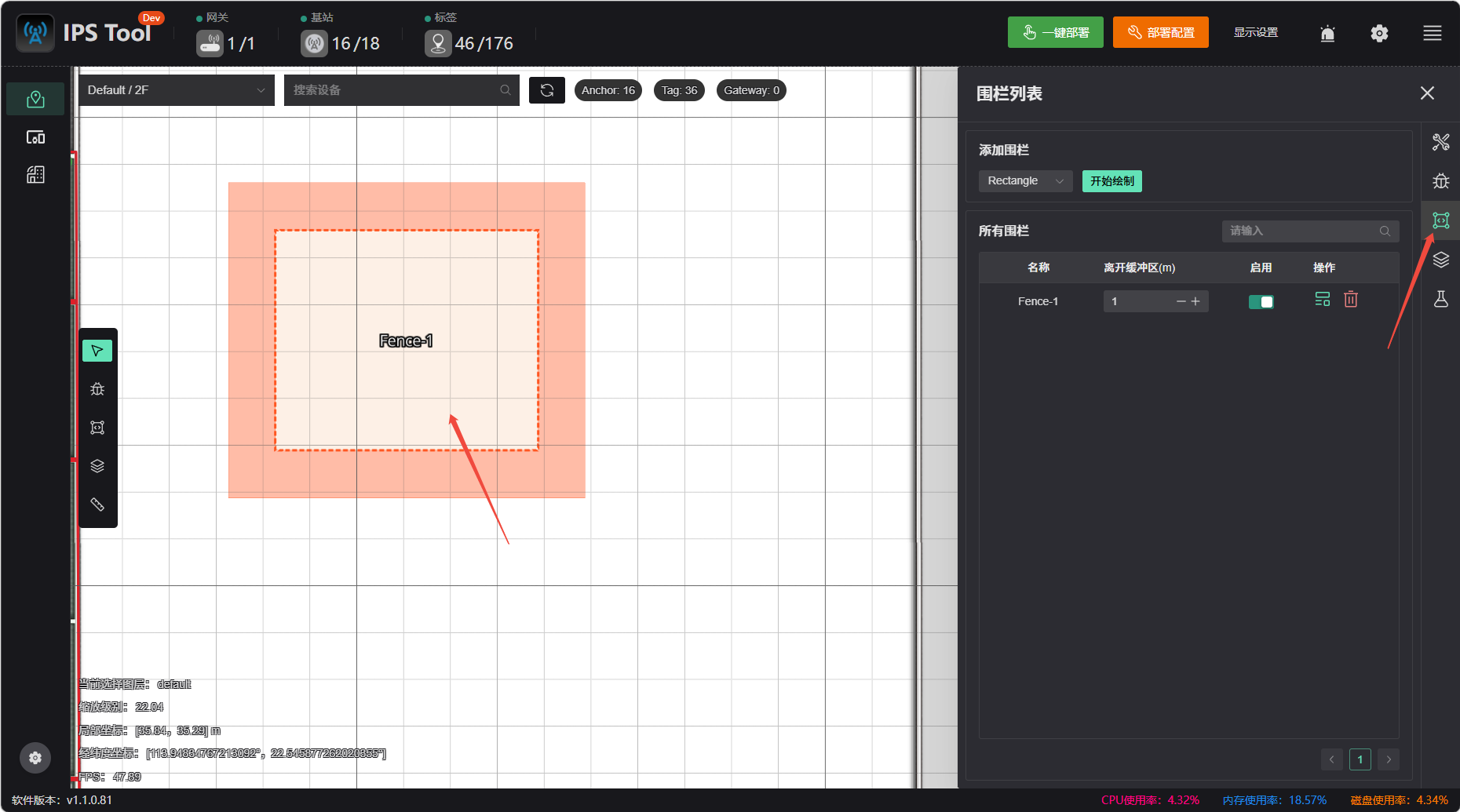
Fence List
When a tag enters an electronic fence area, an alert will be triggered on the PC. Select �“Rectangle” or “Polygon” to draw the fence, and configure which tags to include or exclude, as well as the buffer zone size.
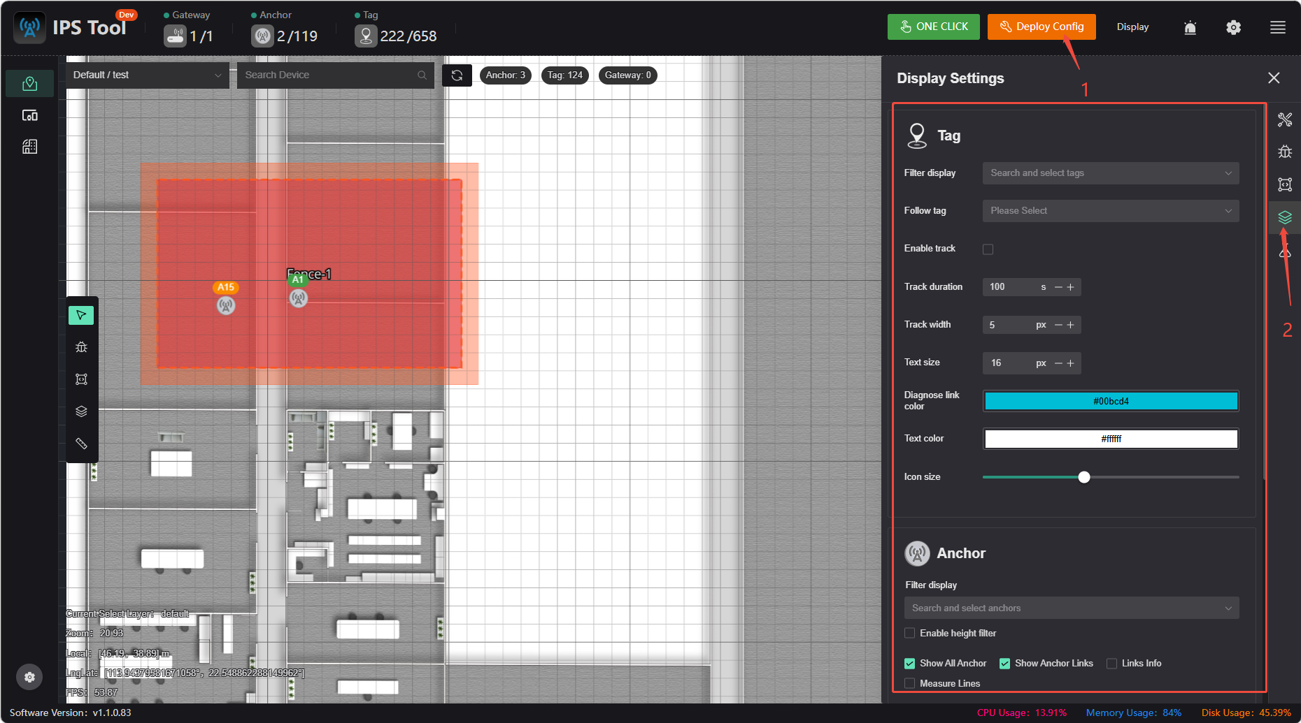
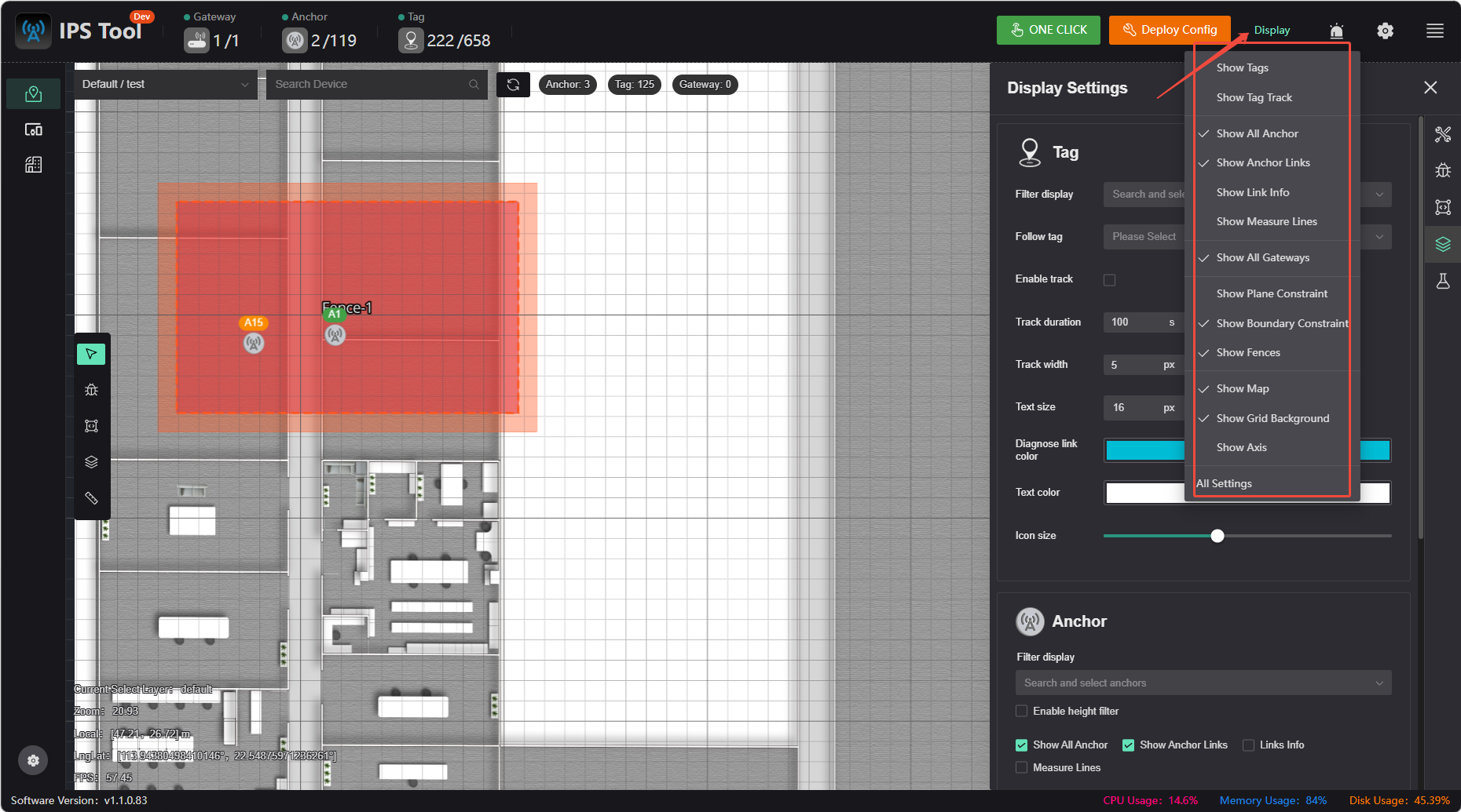
Display Settings
You can filter the display of labels and anchors, and choose whether to show constraints, geofences, and more.
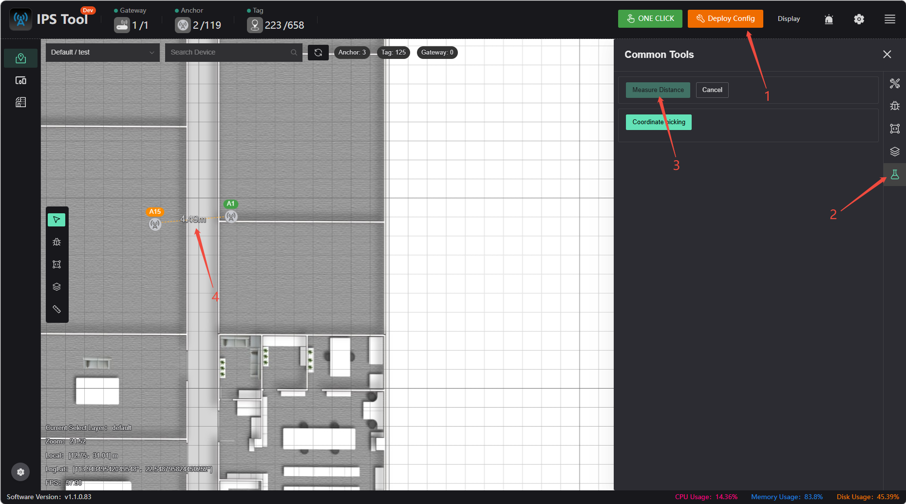
Measure distance