Software Installation Guide
On-site customer deployment / System integrators / Pre-sales and after-sales support
This manual covers the basic deployment process and common troubleshooting methods. For advanced issues, refer to the Quick Troubleshooting Guide.
1. Reading Guide
- This Manual: Explains how to connect, configure, and bring the system online.
- Quick Troubleshooting Guide: Resolves abnormal LED status, offline anchor, and network issues.
👉 Go to Software Troubleshooting
2. Running the Software
Windows Server Deployment
- Create a dedicated directory (for example,
D:\IPS_Tool) and run the IPS Tool executable. - The system will normally open your default browser automatically. You may also manually visit
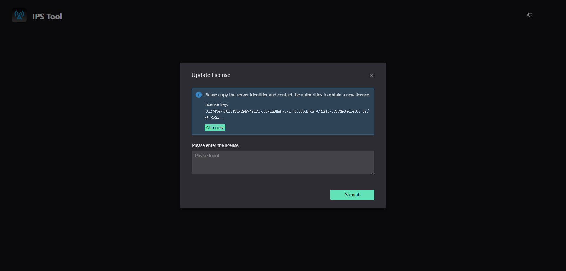
localhost:8080. Google Chrome is recommended. - Copy the license key and send it to a Nooploop engineer to obtain an activation code, then enter the activation code.
Linux Server Deployment
cd <installation_directory>
mkdir ips
cd ips
# Copy the software package provided by Nooploop into this directory
chmod u+x ./ips_tool_v1.1.0.x
sudo ./ips_tool_v1.1.0.x
- On Linux, the browser will not open automatically. Google Chrome is recommended.
- Open
localhost:8080locally, or accessserver_ip:8080from another computer on the same LAN. - Copy the license key and send it to a Nooploop engineer to obtain an activation code.
Notes
- Install and use the software in a dedicated folder. Do not move or rename the folder to avoid data loss.
- When deploying on a new computer or in a new directory, a new activation code is required.
- If important data such as maps is stored in the system, back up the
Datafolder regularly.
3. Pre-Deployment Checklist
- PoE switch (supports IEEE 802.3at)
- Category 5e or higher oxygen-free copper Ethernet cables
- Server (Windows / Linux)
- IPS Tool activated
If any of the above requirements are not met, anchor may fail to power on or come online.
4. Hardware Network Topology
4.1 Solution 1: PoE Switch + anchor + Server (Without Router)
Deployment Steps
-
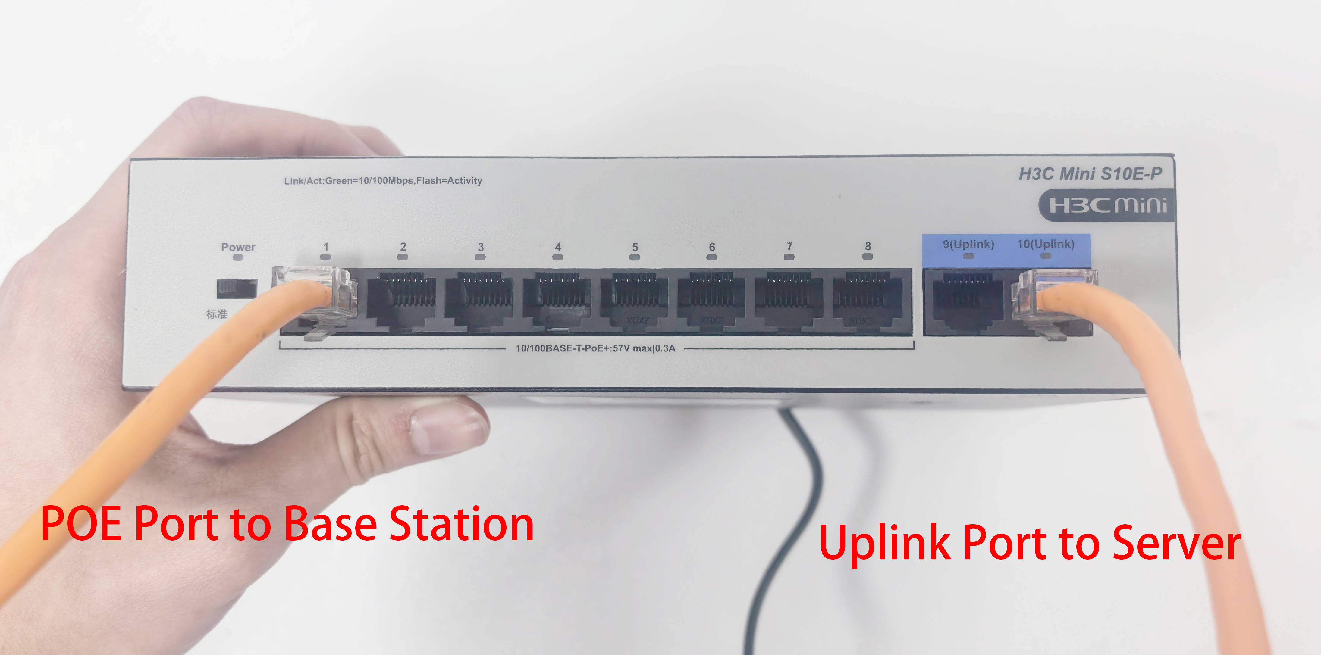
Connect the server to the switch uplink port and connect the anchor to PoE ports.
-
Ensure anchor cascading does not exceed 6 levels. The white
POE-INport is the uplink port and the blackPOE-OUTport is the downstream cascade port.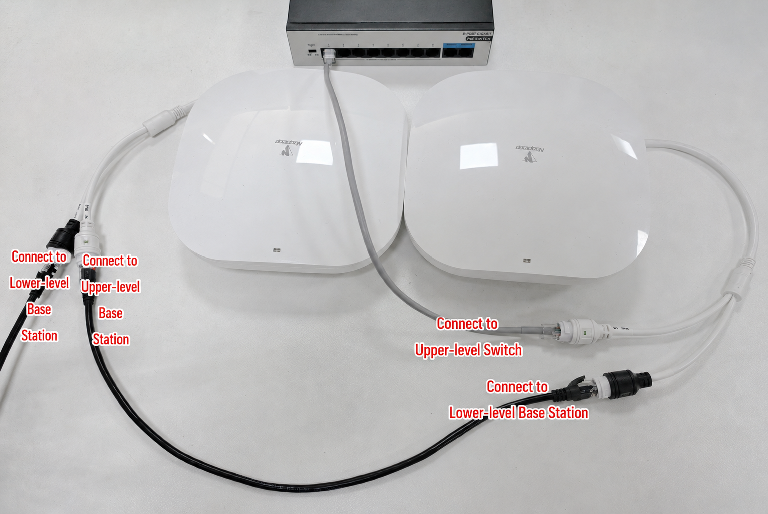
-
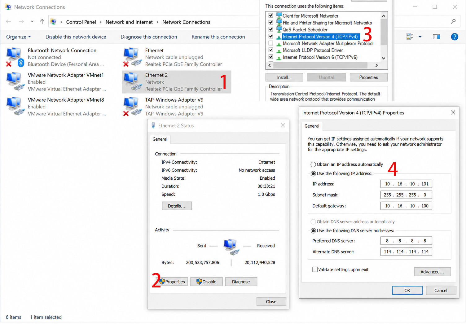
Configure the server Control Panel with a static IP address.
-
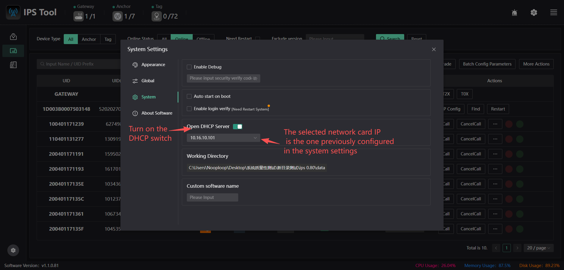
Enable DHCP: System Settings → System → Enable DHCP Server.
👉 For additional issues, see the Software Troubleshooting Guide.
4.2 Solution 2: PoE Switch + Router + anchor + Server
Deployment Steps
-
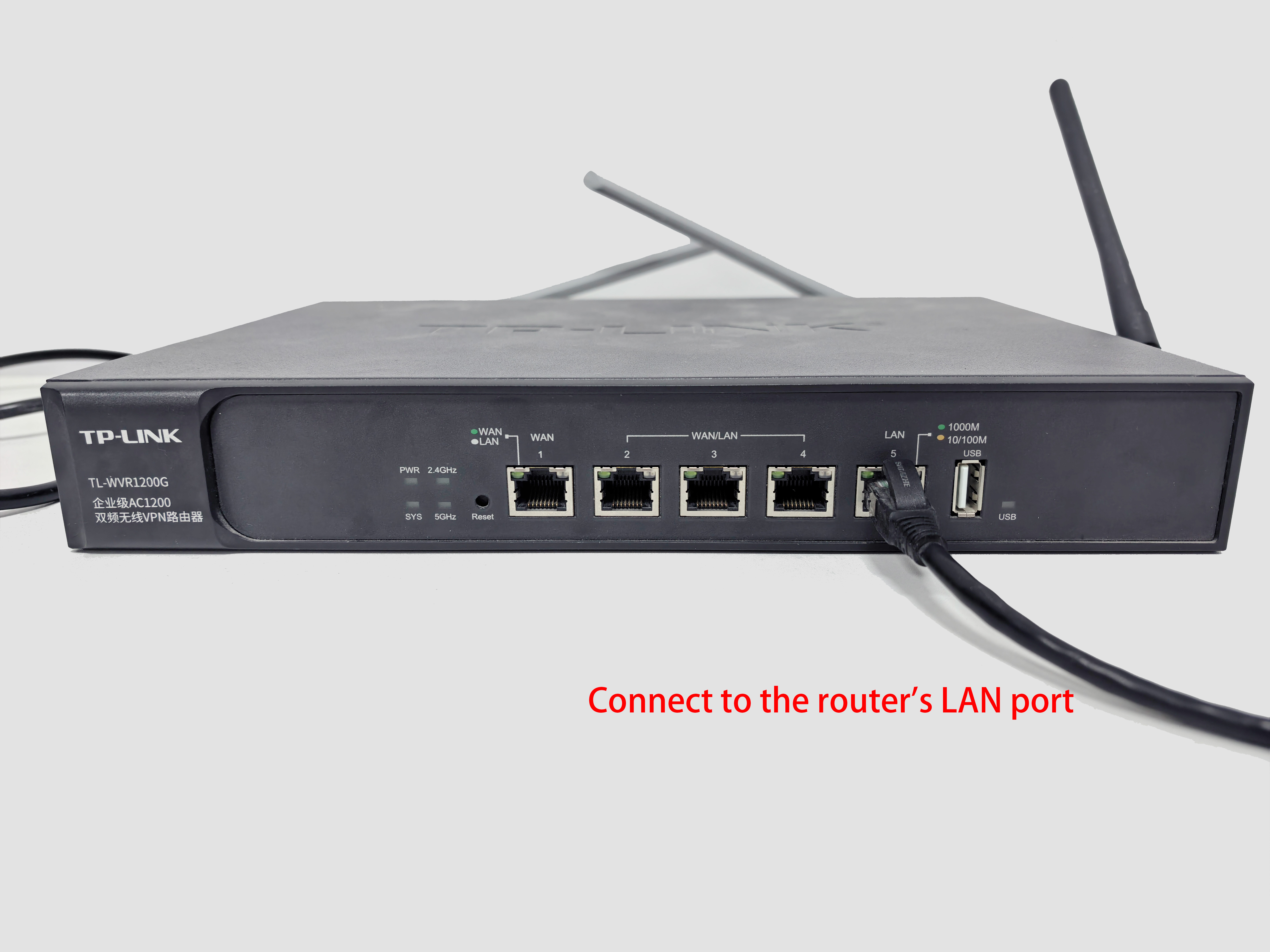
Connect the router to the switch, the server to the switch, and the anchor to the switch (preferably via the uplink port).
-
Cascade anchor from the first anchor's OUT port to the next anchor's POE IN port.
- Maximum cascade depth: 6 levels.
-
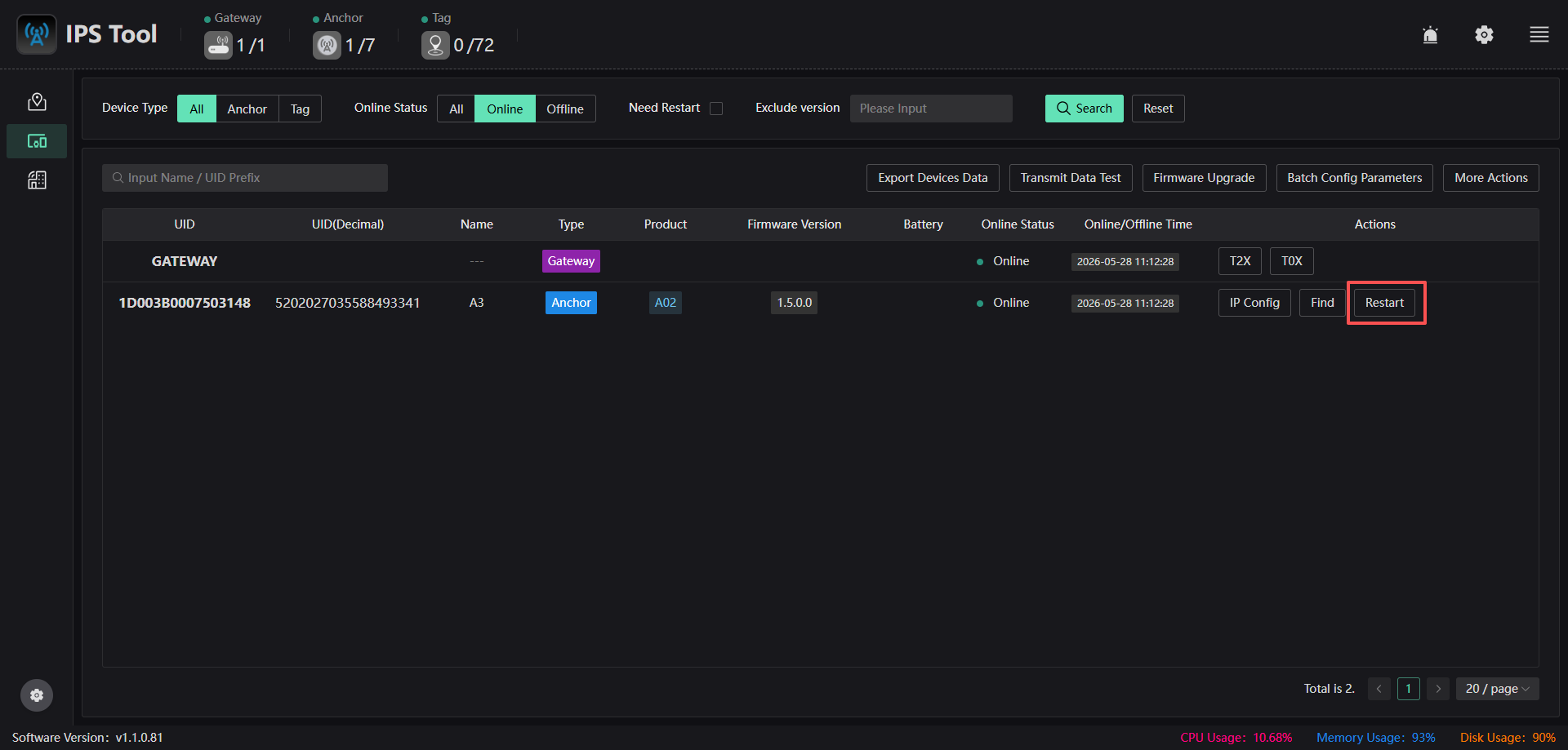
Enter system settings and verify that the number of online anchors displayed in the top bar is correct.
5. Online Status Verification
-
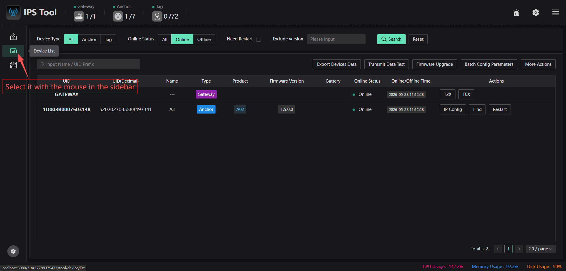
Verify that the number of online anchor shown in the top bar matches the deployed quantity.

-
Verify anchor UIDs in the device list.
-
Check LED status and ensure all anchor display the normal green flashing pattern.
-
Note: Tags will not come online until the anchor have been configured.
👉 If anchor are offline:refer to the Software Troubleshooting Guide
6. Configure a Static IP Address for a anchor
-
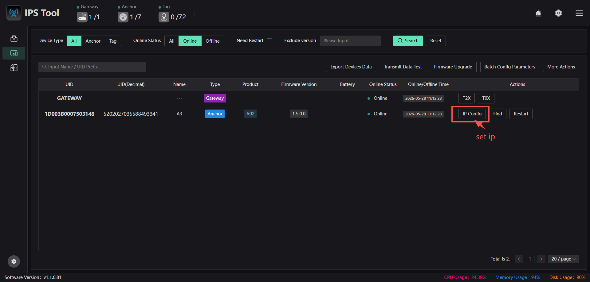
Open the Device List.
-
Select a anchor and click IP Configuration.
-
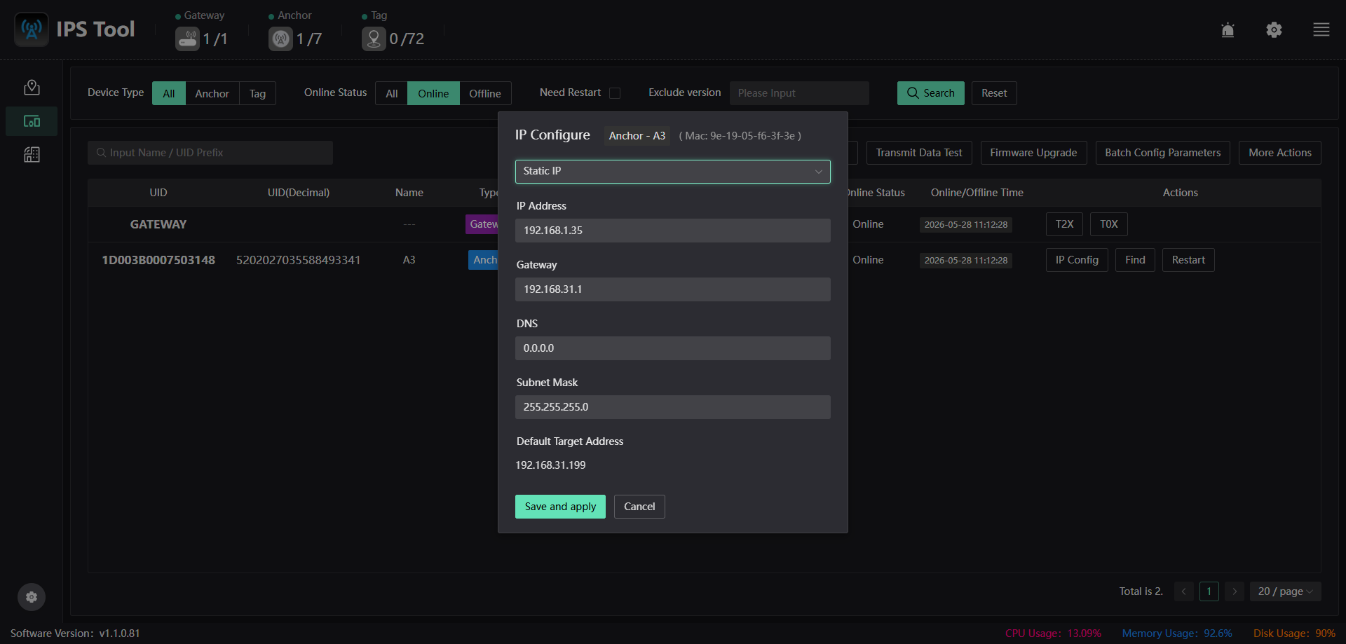
Select Static IP, enter the IP address and related parameters, then save and apply.
-
Click Restart for the anchor in the Device List.