Using Software Features

Common Configurations
Set the Default Location Frequency
A beacon can be shared by multiple zones. The total positioning frequency of each beacon is the sum of the positioning frequencies of the zones in which it participates, and its power consumption is roughly proportional to the total positioning frequency.
There are two modes:
- Power Consumption Priority: Limits the total frequency of each beacon to no more than the target frequency. For example, if set to 1 Hz, and a single beacon is shared by two zones, the maximum frequency for both zones is 0.5 Hz.
- Positioning Priority: The positioning frequency for each zone is limited to the target frequency. For example, if set to 1 Hz, and one beacon is shared by two zones, the total frequency for that beacon is 2 Hz.
Typically, the Power-Saving Priority mode is selected to ensure that the beacon’s minimum battery life meets the required standard.
Adding Beacons to the Map
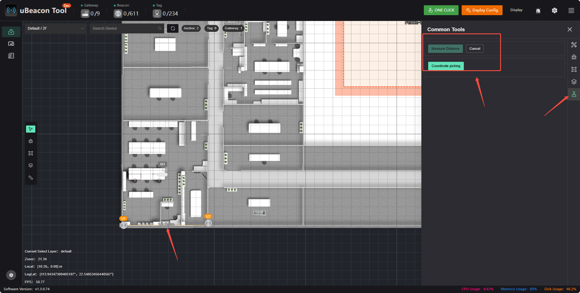
Switch to the Map page in the sidebar and add beacons to the map one by one. The smaller the error in a beacon’s coordinates, the more stable the positioning and the greater its resistance to obstruction. For applications requiring high positioning accuracy, the precision of beacon coordinates must also be correspondingly higher. The Z-coordinate of a beacon is just as important as the X and Y coordinates, but it is often overlooked and requires special attention.
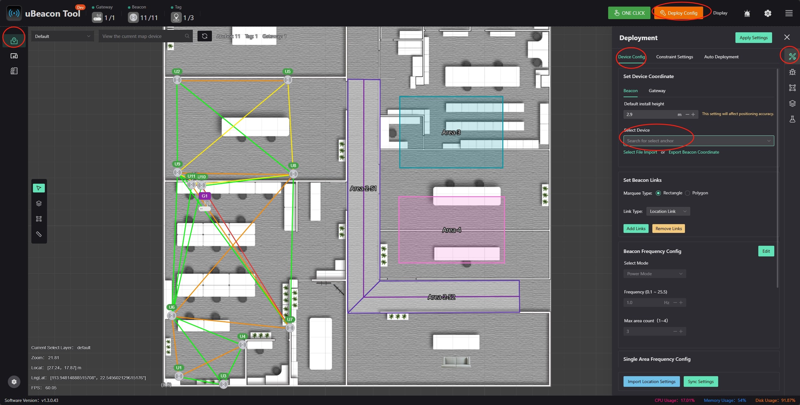
Since positioning is based on distance differences, positioning accuracy gradually decreases outside the beacon’s range; therefore, beacons should be placed as close as possible to the edges of the target positioning area to expand the effective range.
Add a beacon link
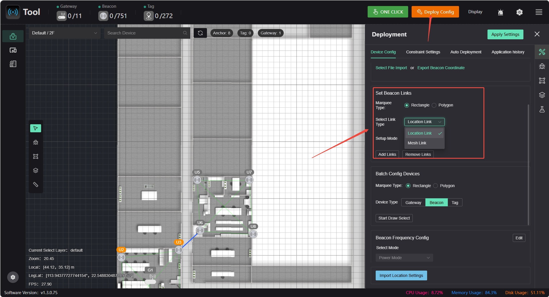
Configure the link relationships between beacons based on actual conditions; there are two types of links
- location_link: A positioning link; connected beacon pairs provide positioning information. This type of link consumes a high amount of power, so obstructions between positioning links should be minimized. Beacons that are spatially within the same area should be connected using positioning links
- mesh_link: A communication link. Connected beacon pairs are responsible only for network connectivity. This type has low power consumption and can tolerate some obstruction, but must still maintain stable communication; severe obstruction that prevents communication is not acceptable.
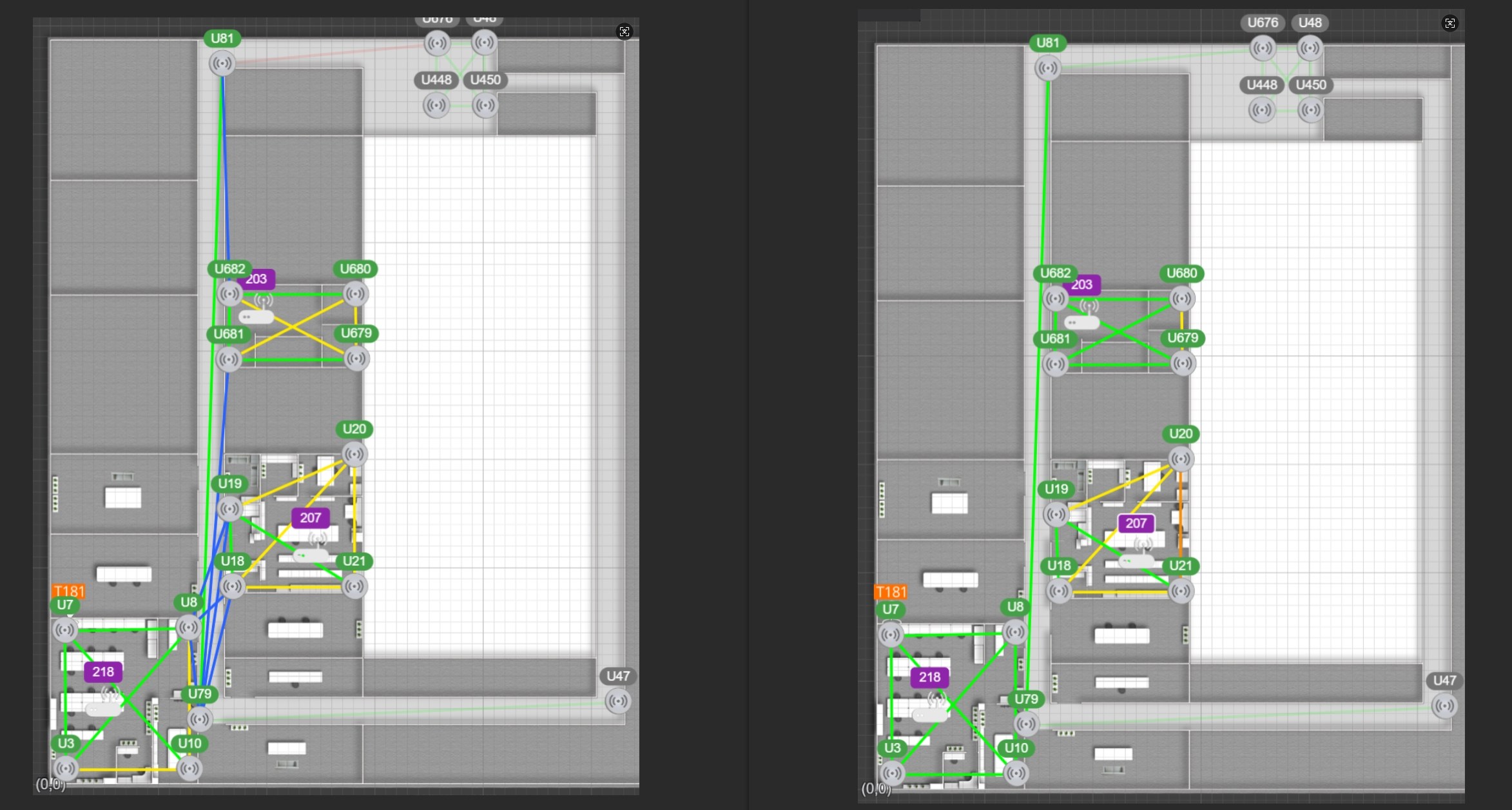
Typically, on a map where different areas are relatively close together and positioning is always required when moving between areas, it is essential to ensure that the beacons on the map are interconnected; otherwise, handover issues may arise, such as significant handover delays or failed handover attempts.
As shown in the left figure below, the blue lines represent mesh_link, which is used solely to connect the various areas. If the blue lines are absent (as in the right figure), the following situation may occur
Suppose a tag powers on and begins operating at location 218. Initially, it may only receive the signal from the beacon at 218. Since the beacon network is not connected, the beacon at 218 is unaware of the existence of other beacons, and the tag cannot obtain this information either. Even if the tag moves into the hallway, as long as it can still receive the signal from the beacon at 218, it will not initiate a high-power search for beacon signals and will therefore not receive signals from other beacons.
Continuing on to room 203, due to obstruction (or a greater distance), the tag can no longer receive the signal from beacon 218. The tag then begins a high-power search for beacon signals, detects the signal from beacon 203, and returns to low-power positioning mode.
Apply Configuration
Once configuration is complete, click 【Application Settings】. If there were any issues with the previous configuration, an error will be displayed when the changes take effect. Fix the problem based on the error message. Once the changes are successfully applied, all indicators will turn orange, indicating that the parameters are pending synchronization. When the indicators turn green again and the exclamation mark disappears, it means that parameter synchronization is complete.
Equipment List
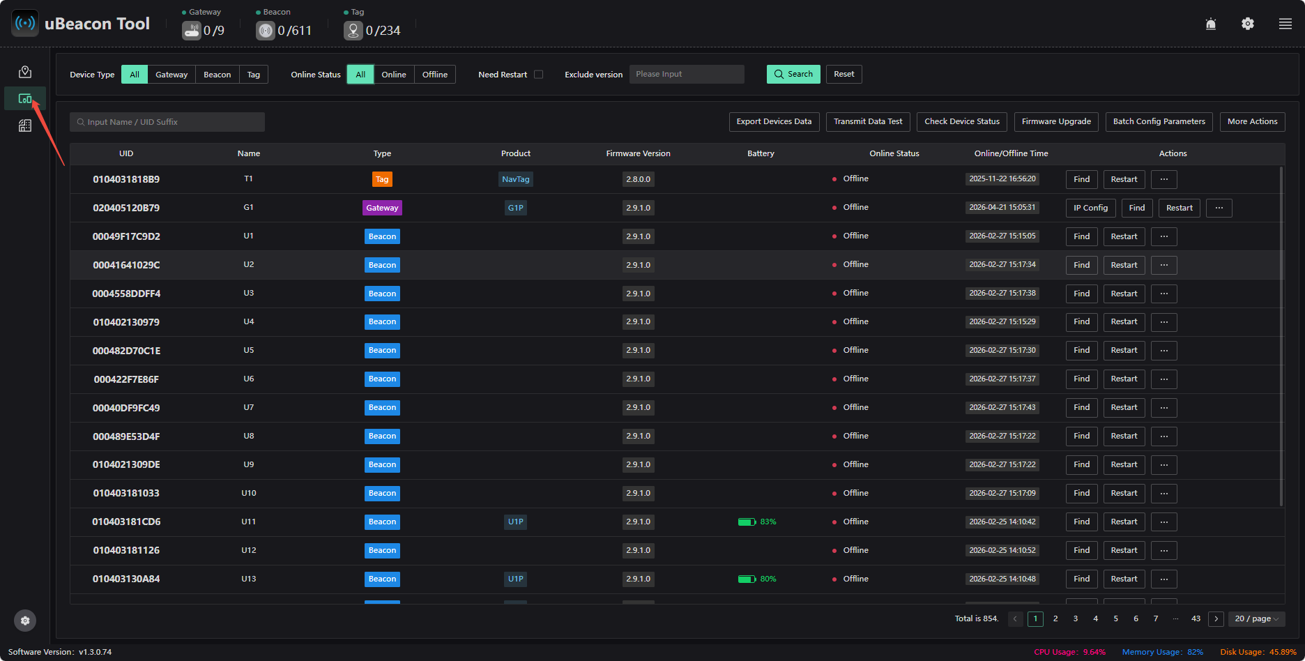
Click 【Device List】 on the left to view devices, check for firmware updates, configure parameters in bulk, view device details, and more.
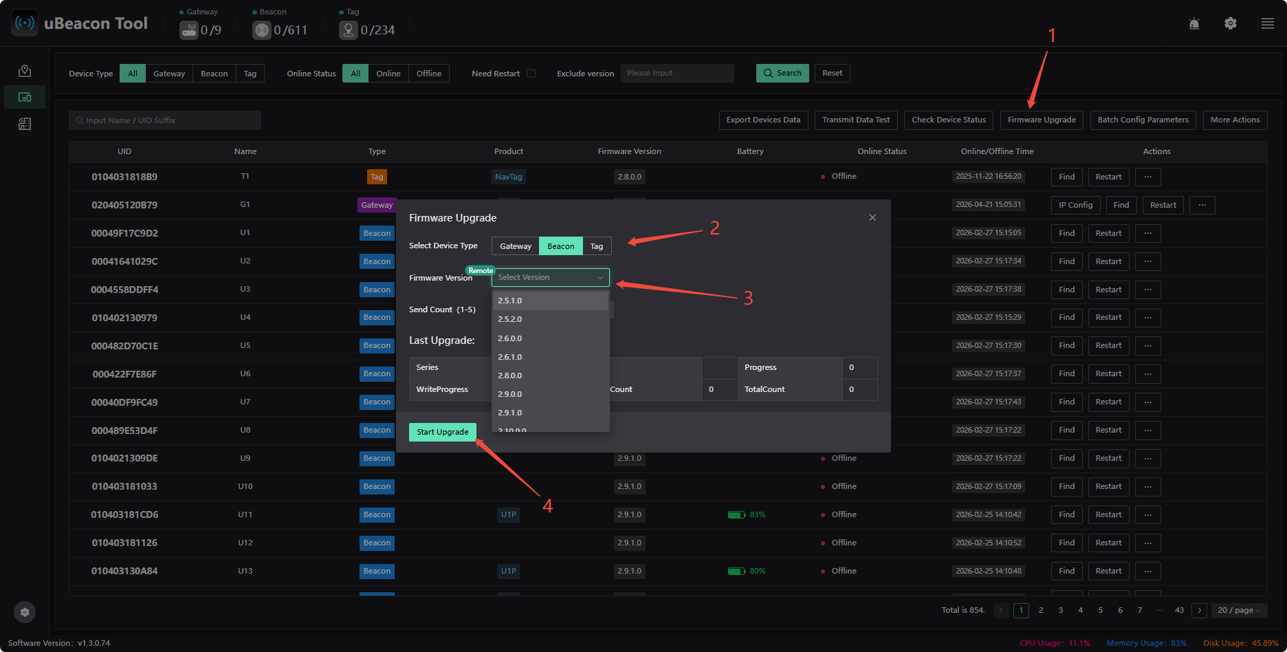
Firmware Update
Click 【Firmware Update】 to update the firmware for beacons and tags. Note: Please contact the official support team for confirmation before updating.
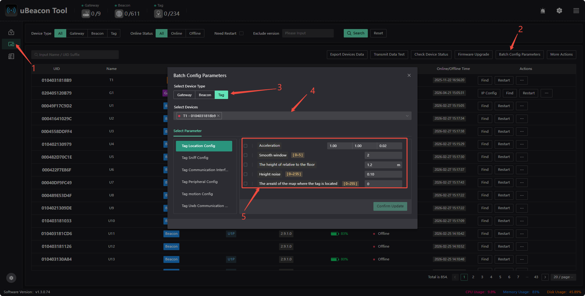
Batch Configuration Parameters
Click 【Batch Configure Parameters】 to configure parameters for all or specified launch beacons and tags in bulk.
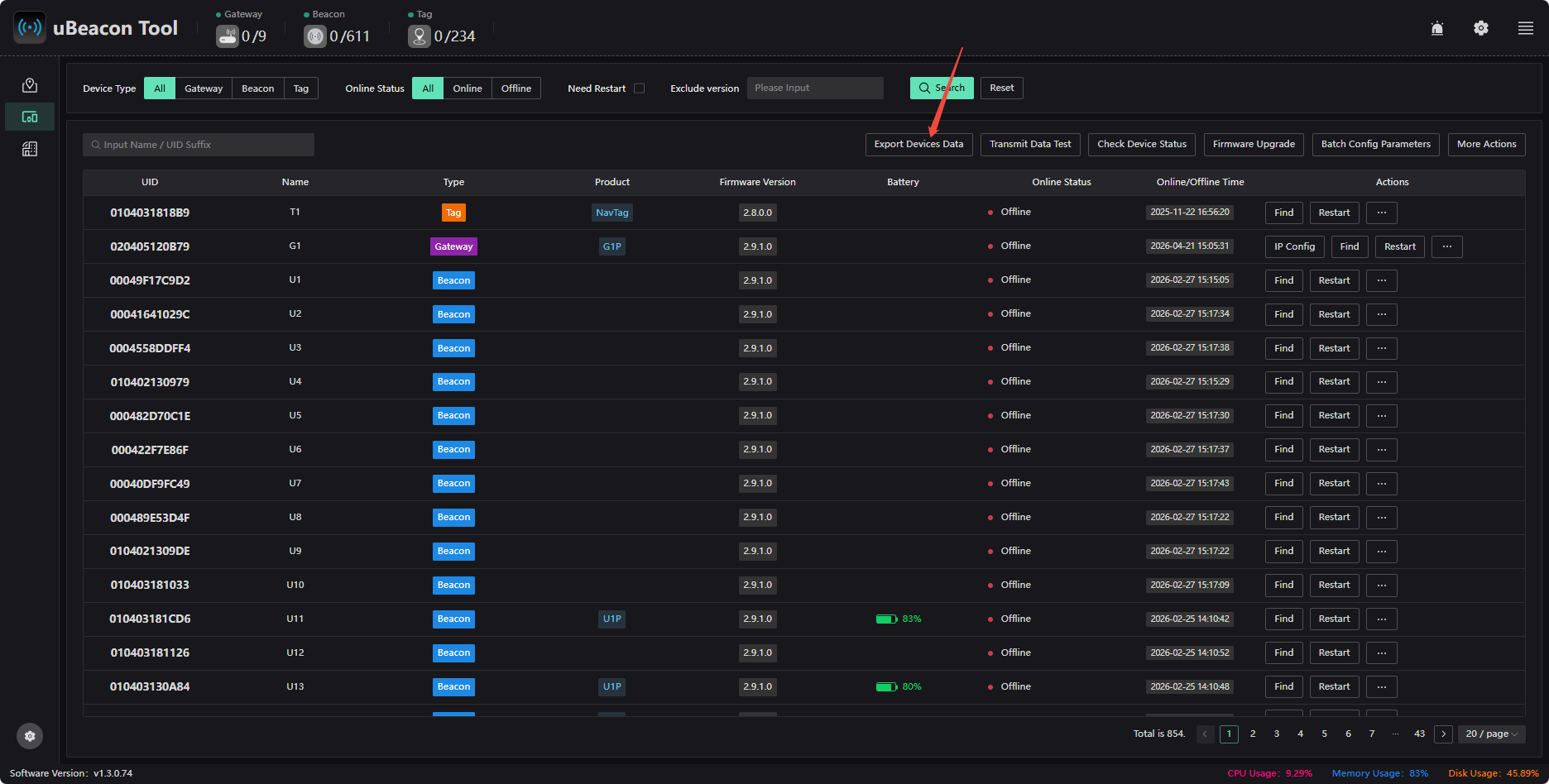
Export Device Information
Gateway Destination IP Configuration
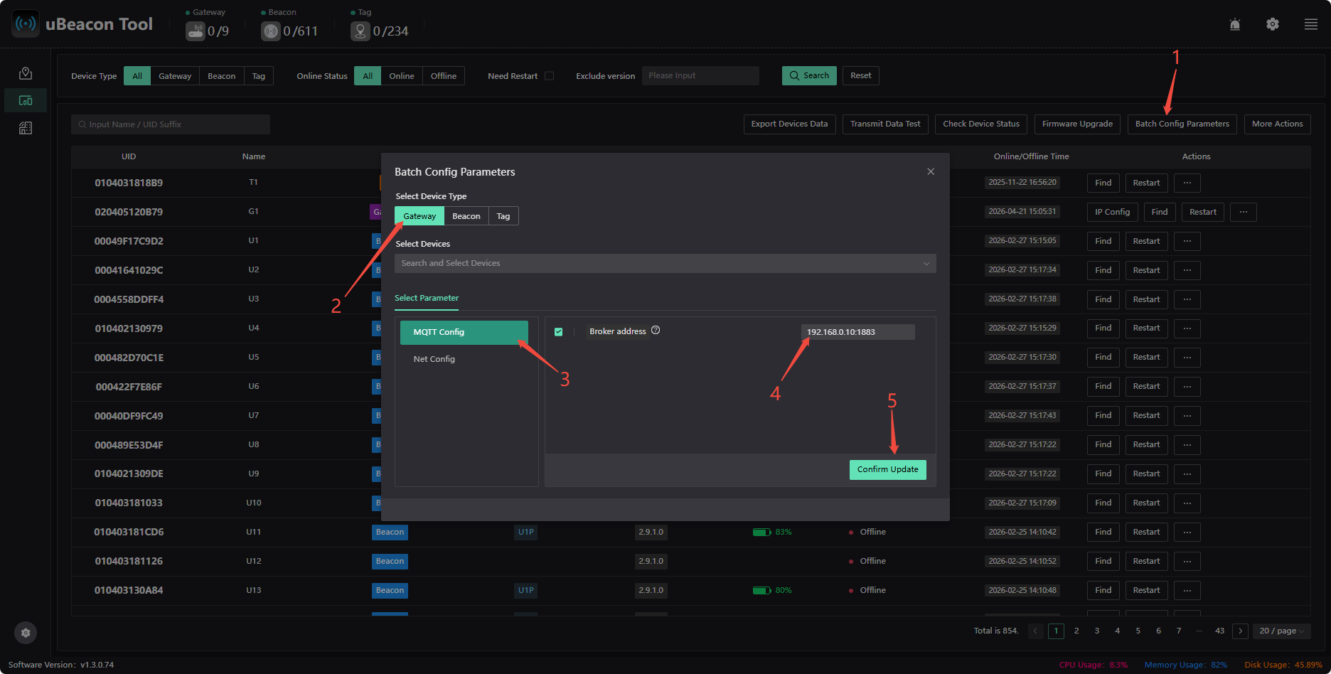
Change the gateway server IP (ensure network connectivity): Enter the new server IP address in the “Server TCP Address” field (leave port 1883 unchanged), click 【Confirm Update】, then restart the gateway device, and finally change your computer's IP address. Note: The gateway's default reporting address is xxx.xxx.xxx.199
Static IP Configuration for the Gateway
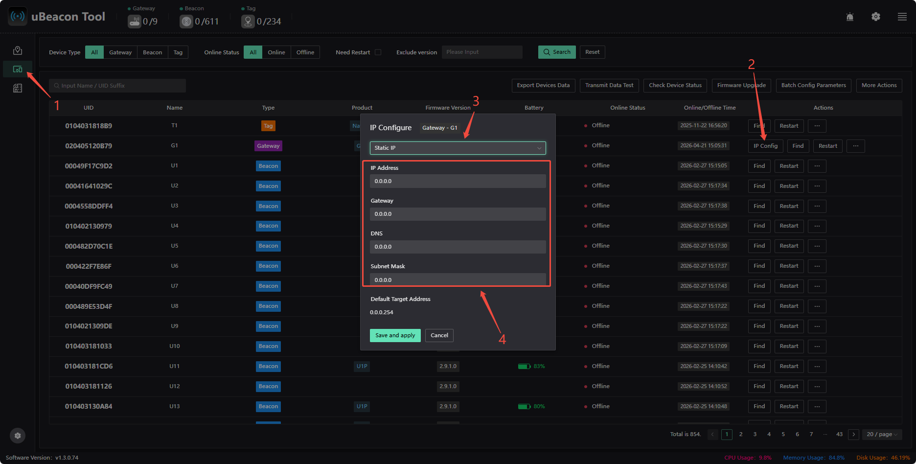
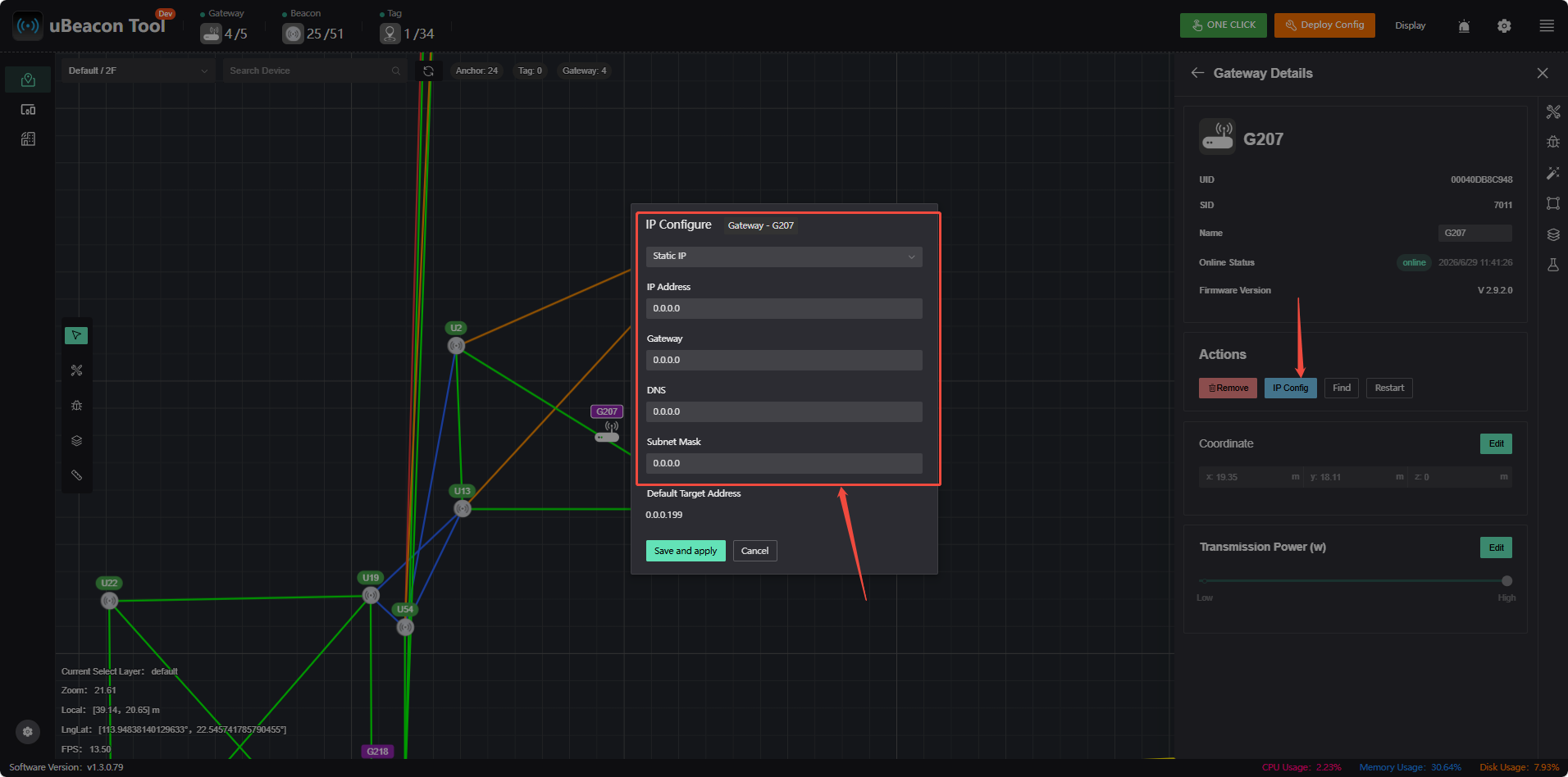
IP addresses are assigned via DHCP by default, but you can also assign static IP addresses. Follow these steps:
- Configure a static IP in the device list
- Click a beacon on the map to configure a static IP
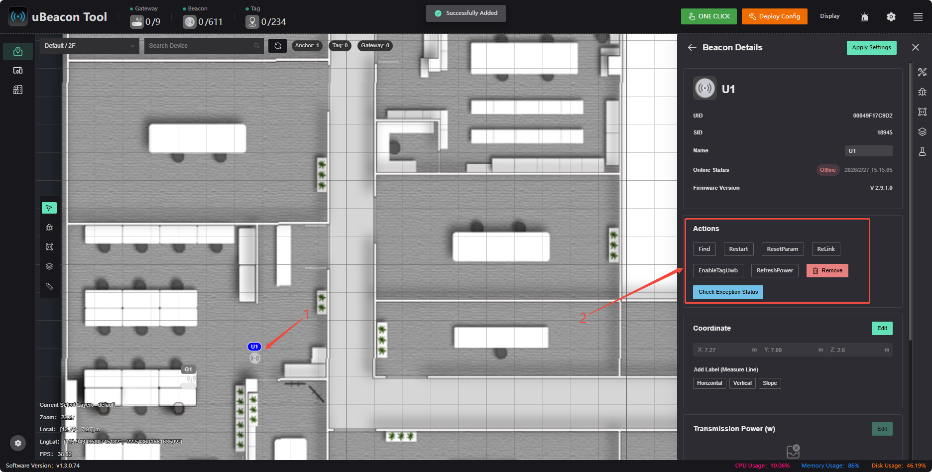
Find, restart the device, etc.
- Device List Operations
- Clicking a Device on the Map
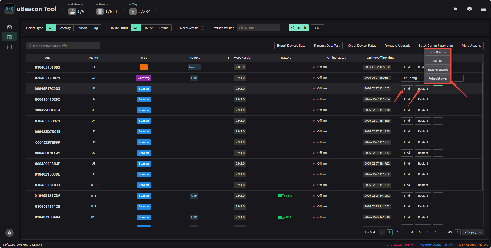
Find:After clicking 【Find】, the corresponding device will flash, making it easier to locate the specified device.
Restart: Click 【Restart】 to restart the device.
ReLink: Click 【ReLink】 to reconnect the link.
EnableTagUwb: Enable the UWB backhaul function.
RefreshPower: Synchronize the display and refresh the transmission power. When the transmission power is modified, click this button to ensure the displayed value matches the actual operating value.
RefreshHardwareInfo: Reset the tag parameter information.
Equipment Details
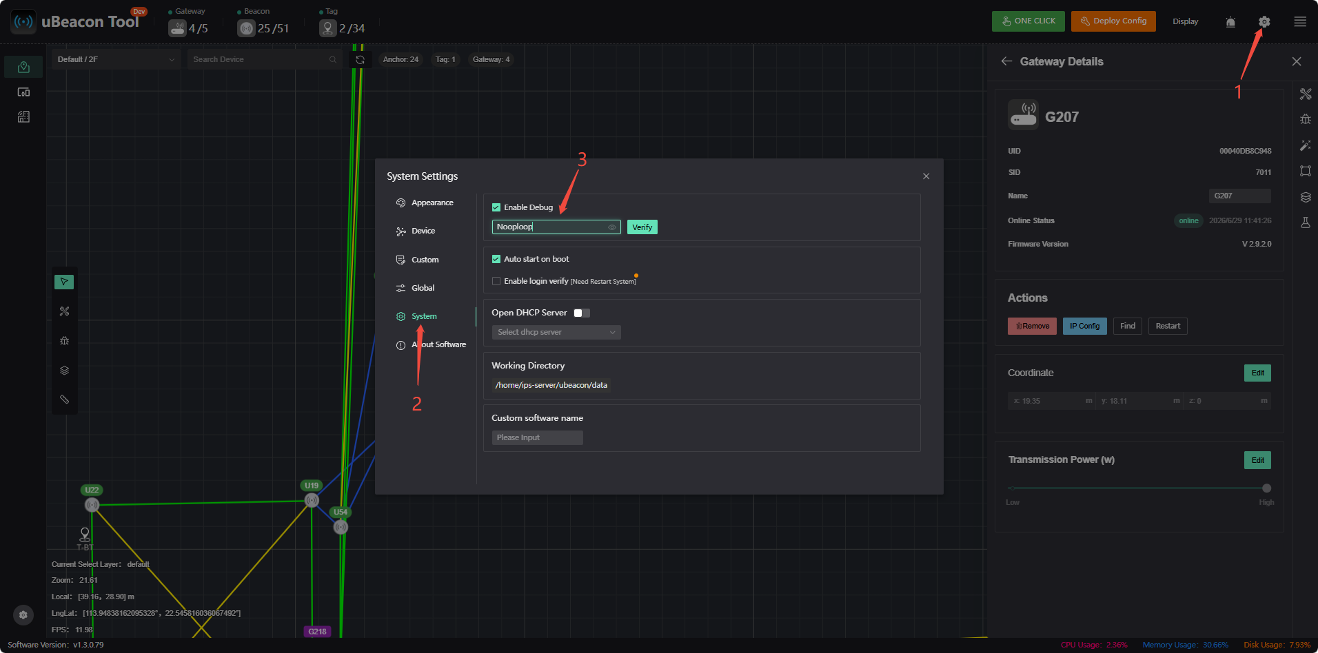
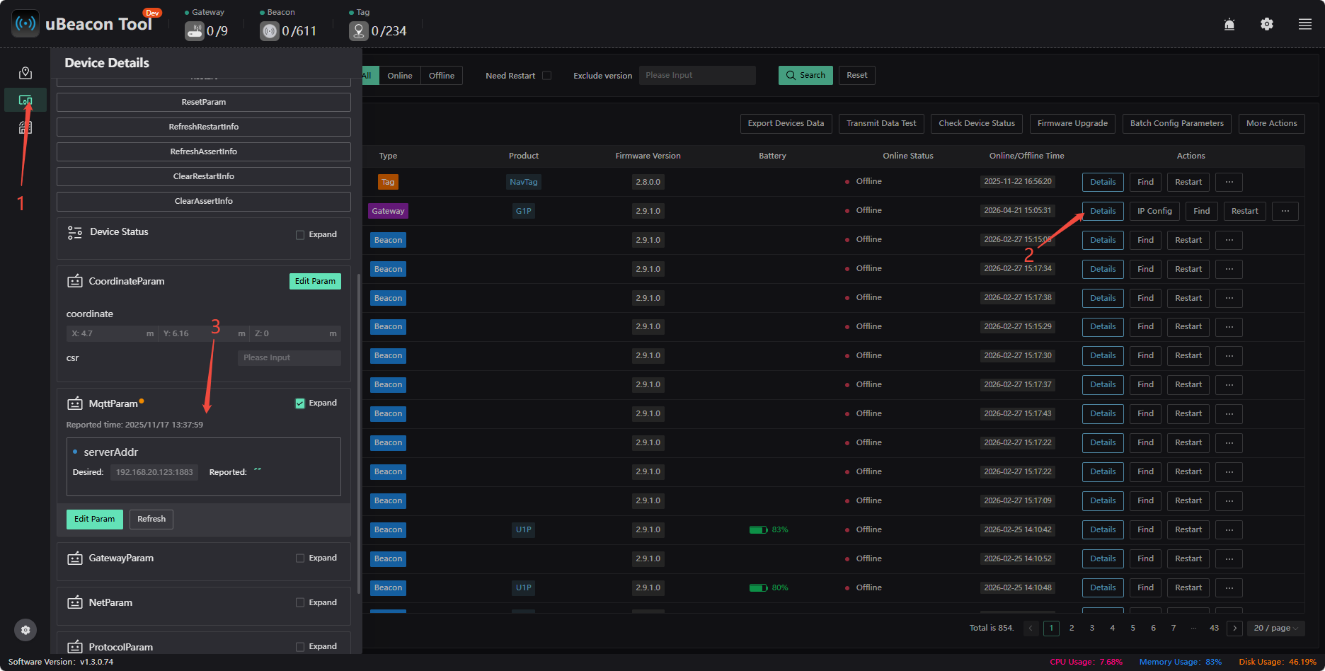
To view device details, you must first click “Settings,” enable debugging, and enter the password “Nooploop.” Once debugging is enabled, click 【Device Details】 to view detailed information about the gateway, beacon, and tags.
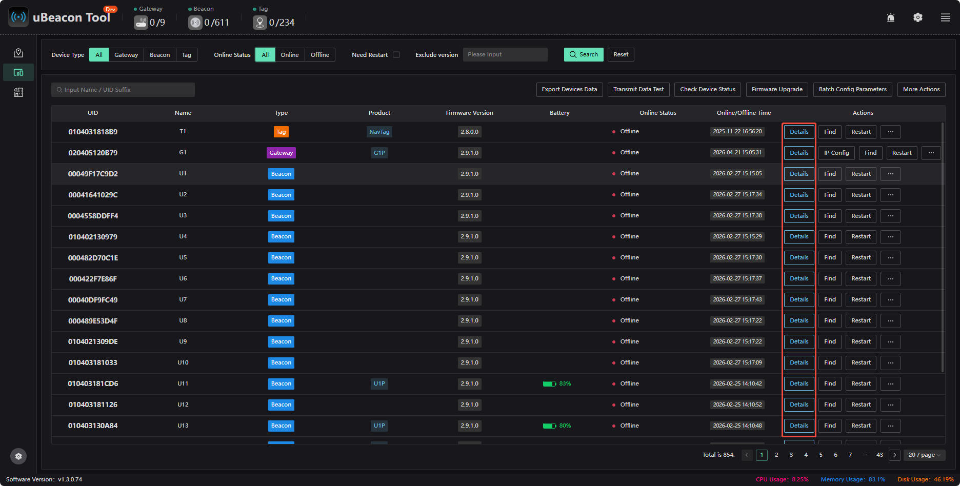
Check the IP address of the target server that the gateway is actually pointing to
Constraint Settings
By default, the map has a plane constraint that constrains the label height to the desired height. There are also several types of constraint areas that you can choose to add. Constraint areas are unrelated to positioning areas; simply add them where needed. The scope of a constraint area defines the range within which the constraint takes effect; the constraint only applies when the label’s coordinates are within that scope. Therefore, you should adjust the scope based on the actual situation and your needs.
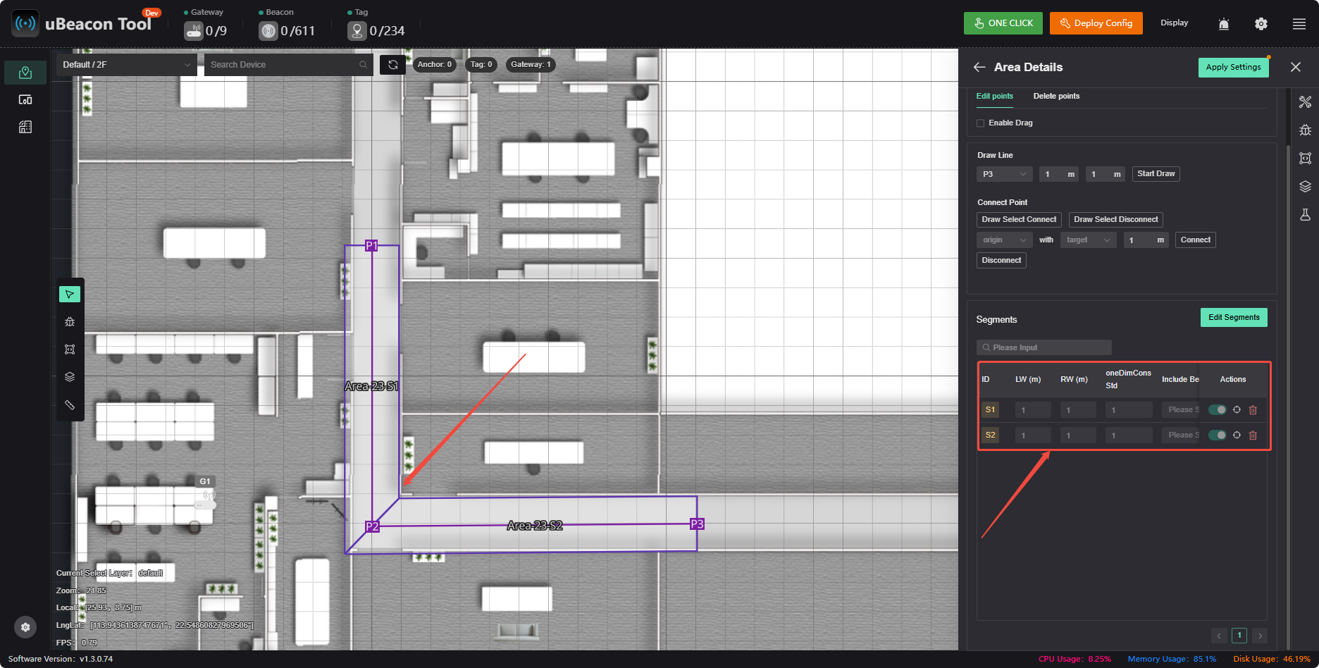
One-dimensional constraint
This is typically used for one-dimensional regions. Due to the underdetermined nature of one-dimensional regions, constraints must be added; otherwise, there will be no unique solution. When drift in localization is detected at certain locations due to occlusion, one-dimensional constraints can also be added to restrict the localization results to the desired positions (for example, by adding constraints at the region boundaries to prevent the localization results from drifting outside the region).
The constraint standard deviation indicates the strength of the constraint; the smaller the standard deviation, the stronger the constraint and the greater the adhesive force. If the constraint is too strong, it may prevent the object from leaving the constrained area from the side or cause a significant delay in leaving it. The standard deviation is typically set to half the width.
Two-dimensional constraints
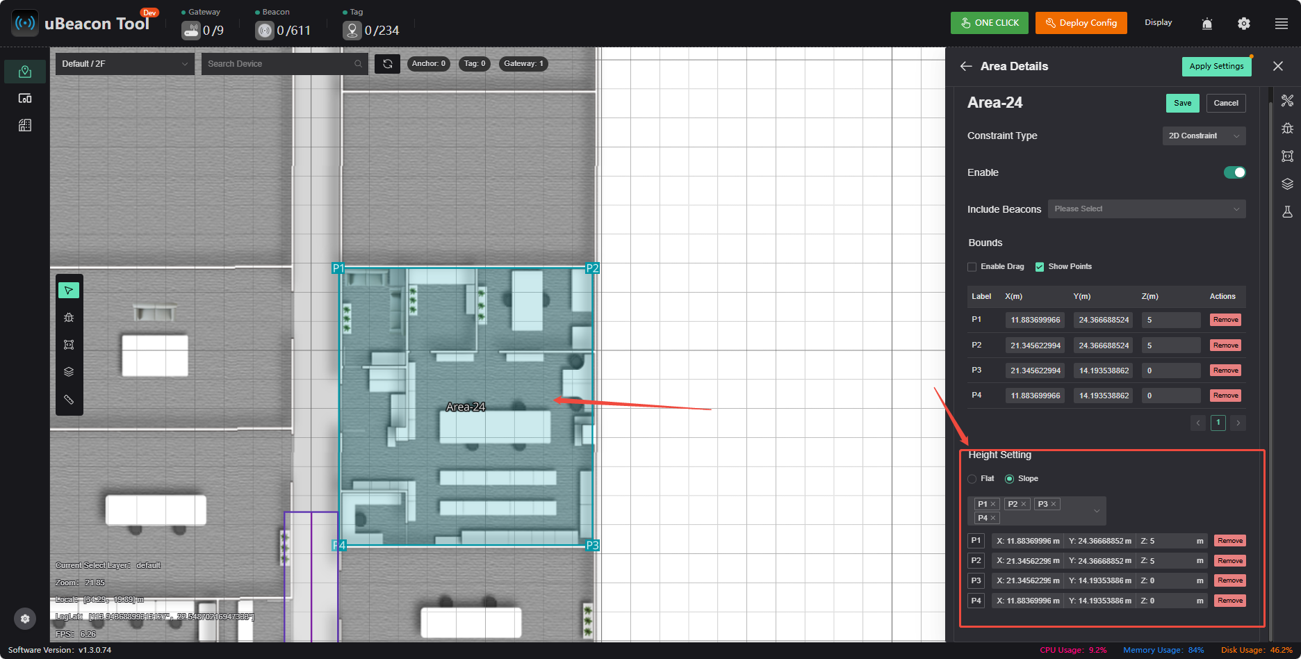
If a region contains platforms or slopes at elevations different from the map’s zero plane (and with significant elevation differences), surface constraints must be drawn to simulate those platforms or slopes. This ensures that when labels are moved to the corresponding positions, their elevations adjust accordingly, which helps improve XY accuracy.
3D Constraints
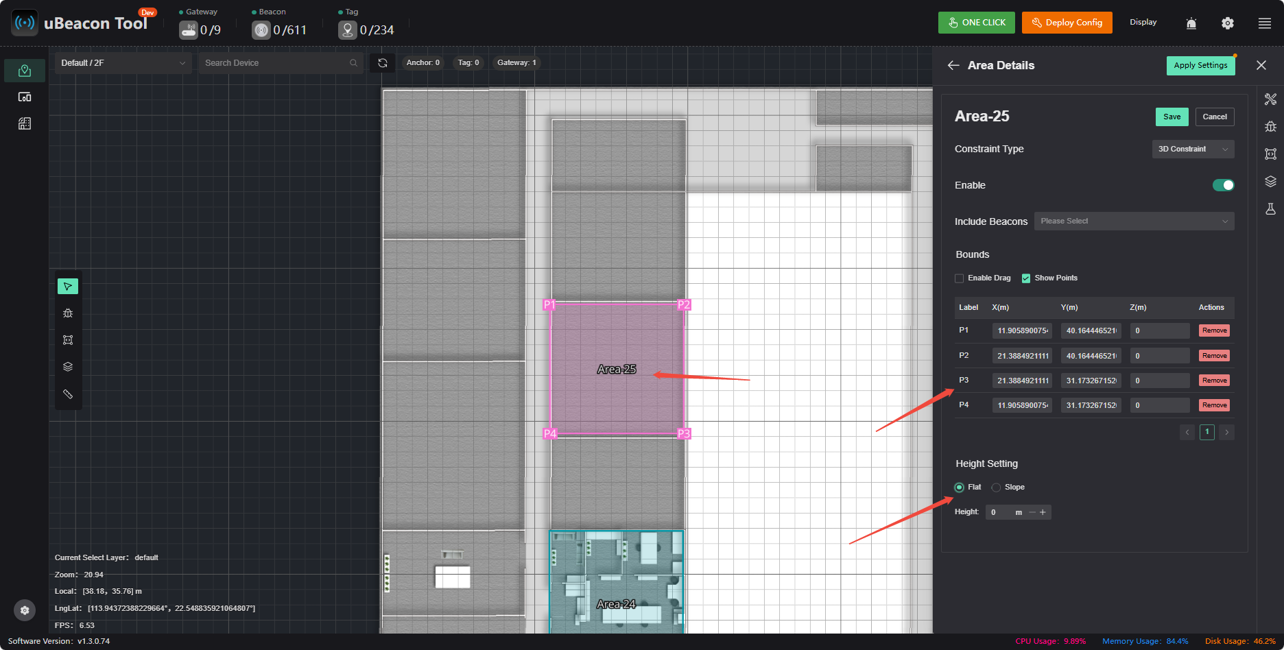
This is used in areas where only precise 3D coordinates are required, but beacons must also be added to the corresponding areas. The height difference in the Z-axis should be similar to that in the XY axes. For example, if a 5×5 room requires 3D positioning, the recommended deployment is to place four beacons on the ceiling and four on the floor, and to configure 3D constraints.
Boundary Constraints
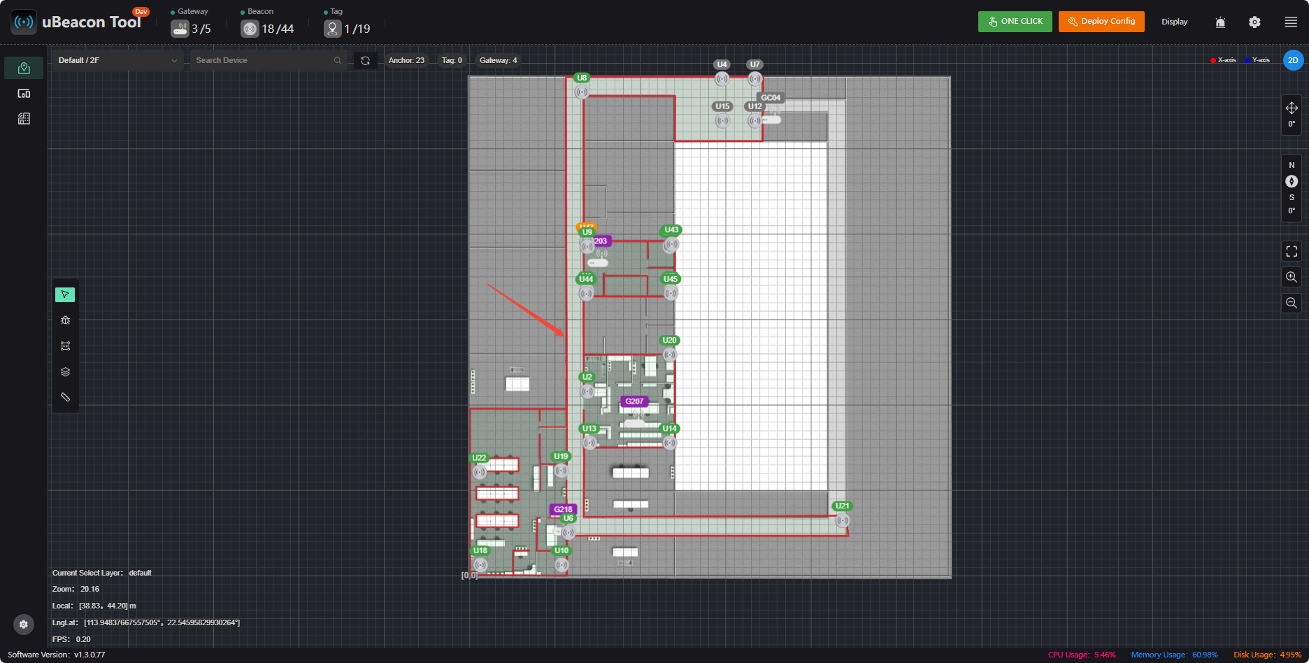
Based on the actual physical environment, one or more closed areas can be predefined on the map. The system will use these areas as the valid positioning range and intelligently correct the real-time coordinates returned by the tags to ensure they are always displayed within a reasonable spatial range
- Effectively suppresses non-line-of-sight errors caused by signal reflection, obstruction, and other factors, preventing tag locations from appearing in unreasonable areas outside obstacles such as walls and partitions (i.e., the “wall-penetration” phenomenon), thereby enhancing the physical credibility of the positioning trajectory.
- When positioning signals experience temporary fluctuations or partial beacon signal loss, this feature constrains the tag’s position within known valid areas, preventing meaningless, significant drifts in location data and ensuring positioning continuity.
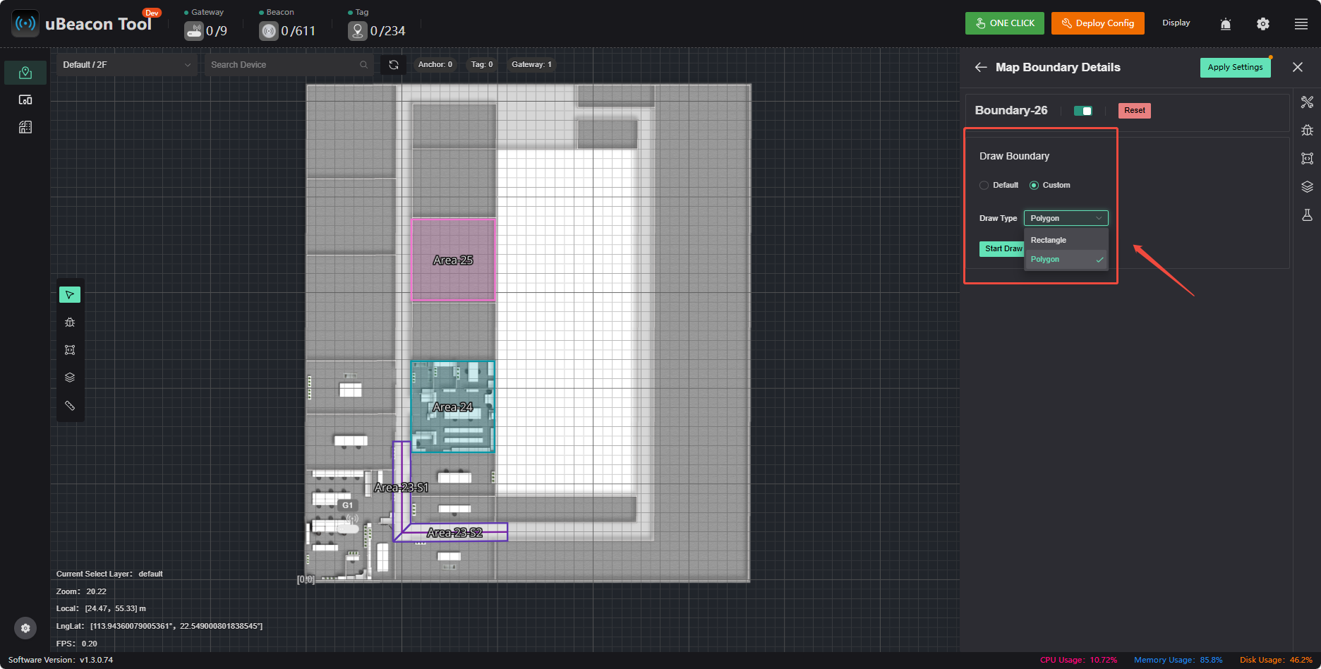
- Click to enable 【Boundary Constraints】
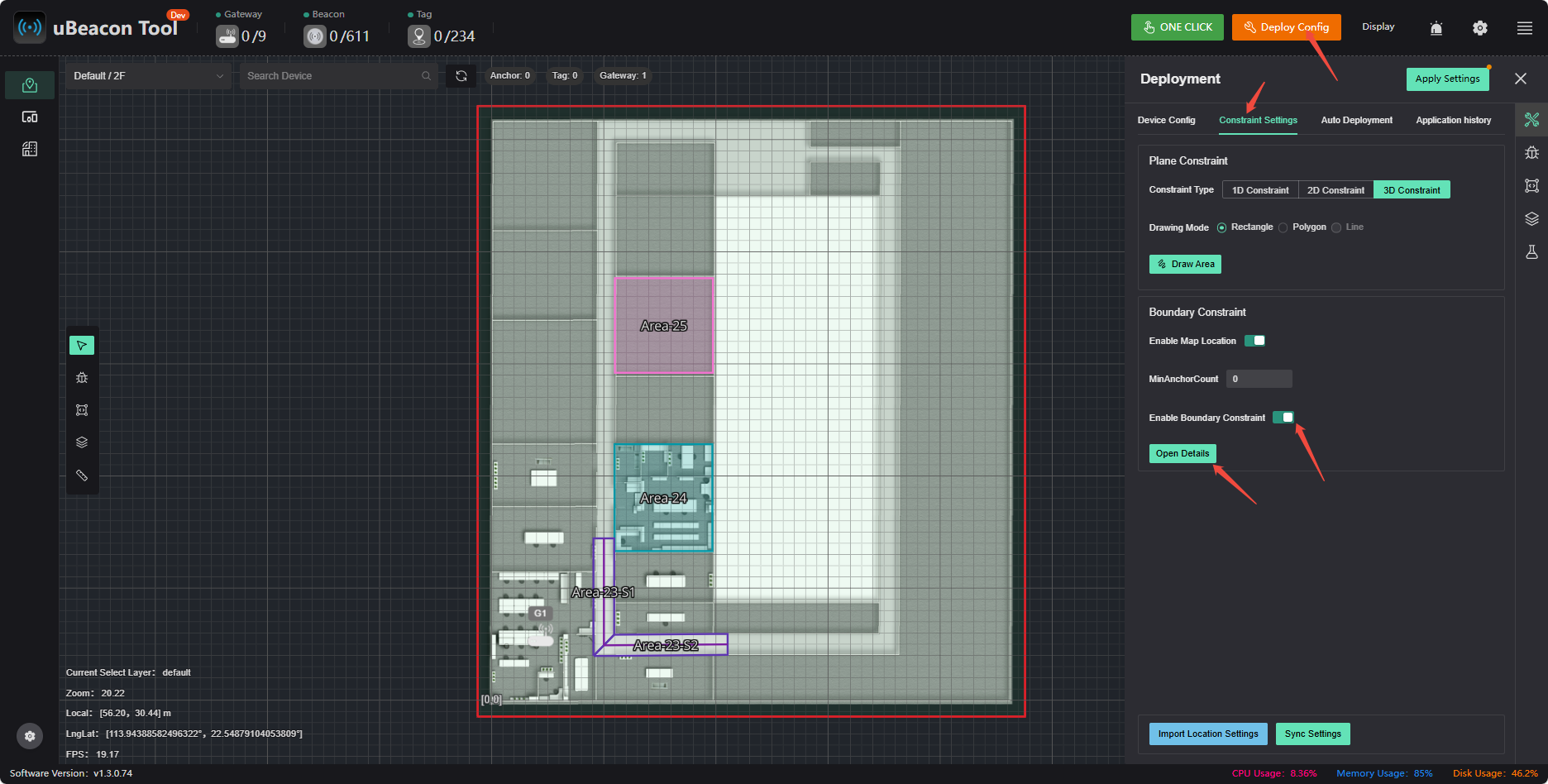
- Click 【Custom Drawing Method】 to draw the boundary
More Features
Application History
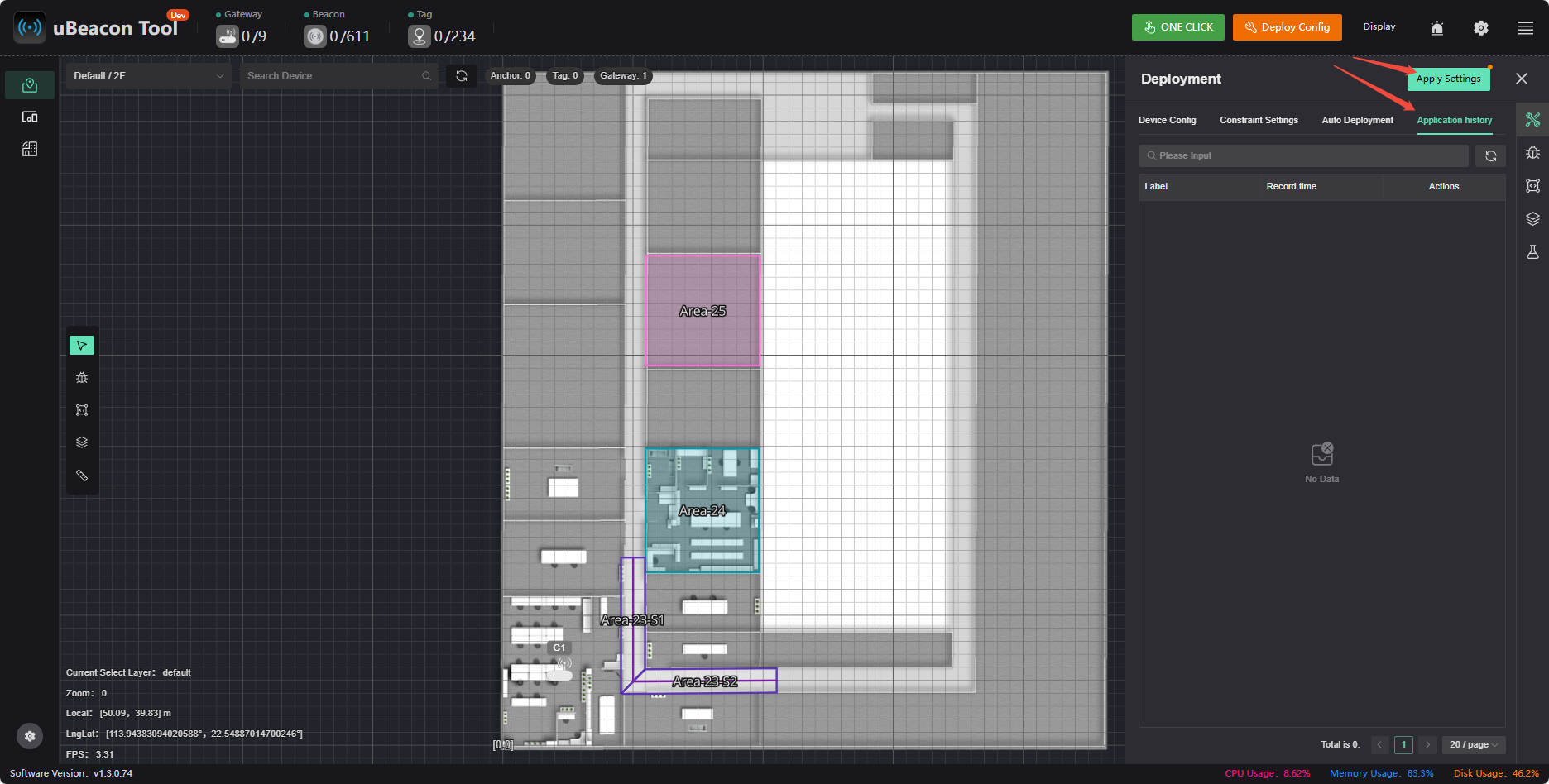
If you make a mistake, you can undo it in 【App History】. Tapping the 【App Settings】 button creates a new entry.
List of Fences
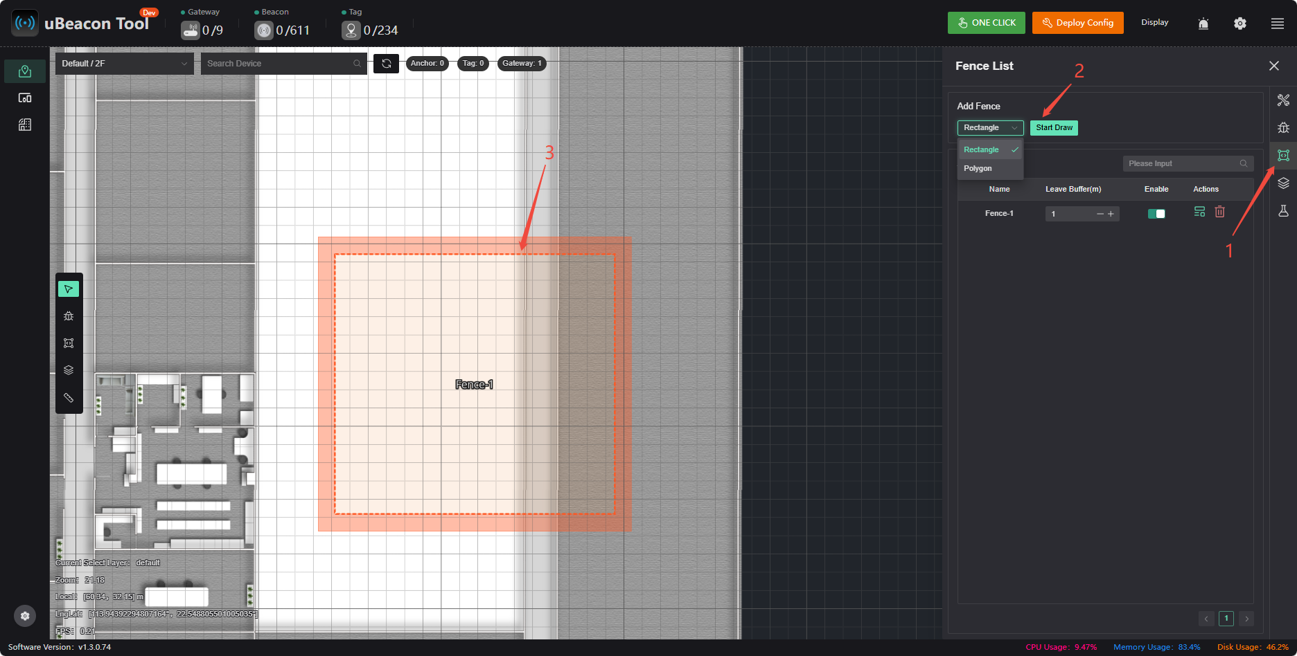
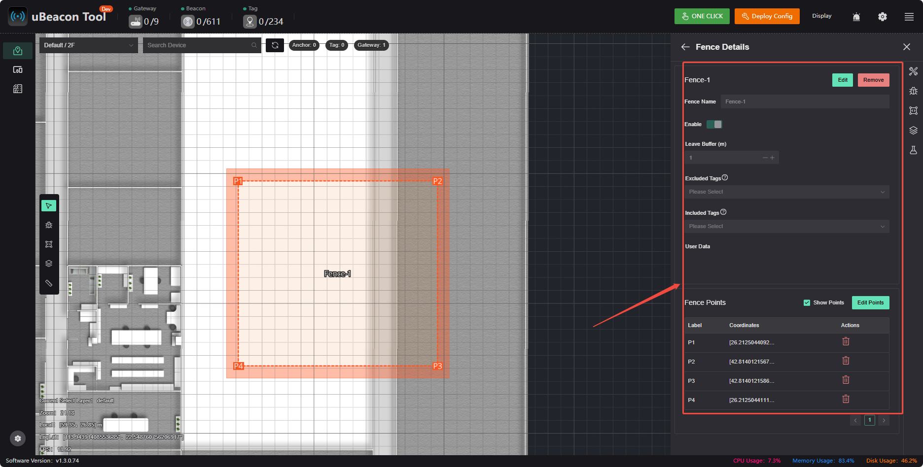
When a tag passes through a geofence area, an alert will be triggered on the PC, and geofence data will be sent via the API. You can choose to draw a rectangle or a polygon to set which tags to include or exclude, as well as the size of the buffer zone.
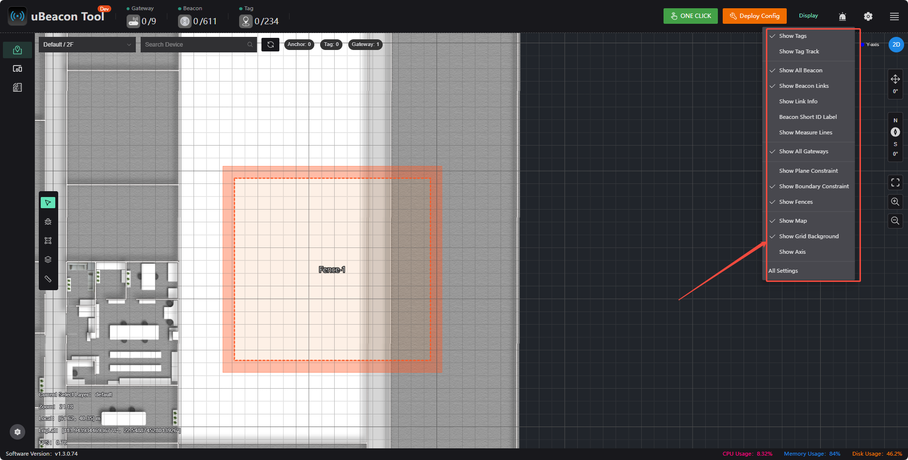
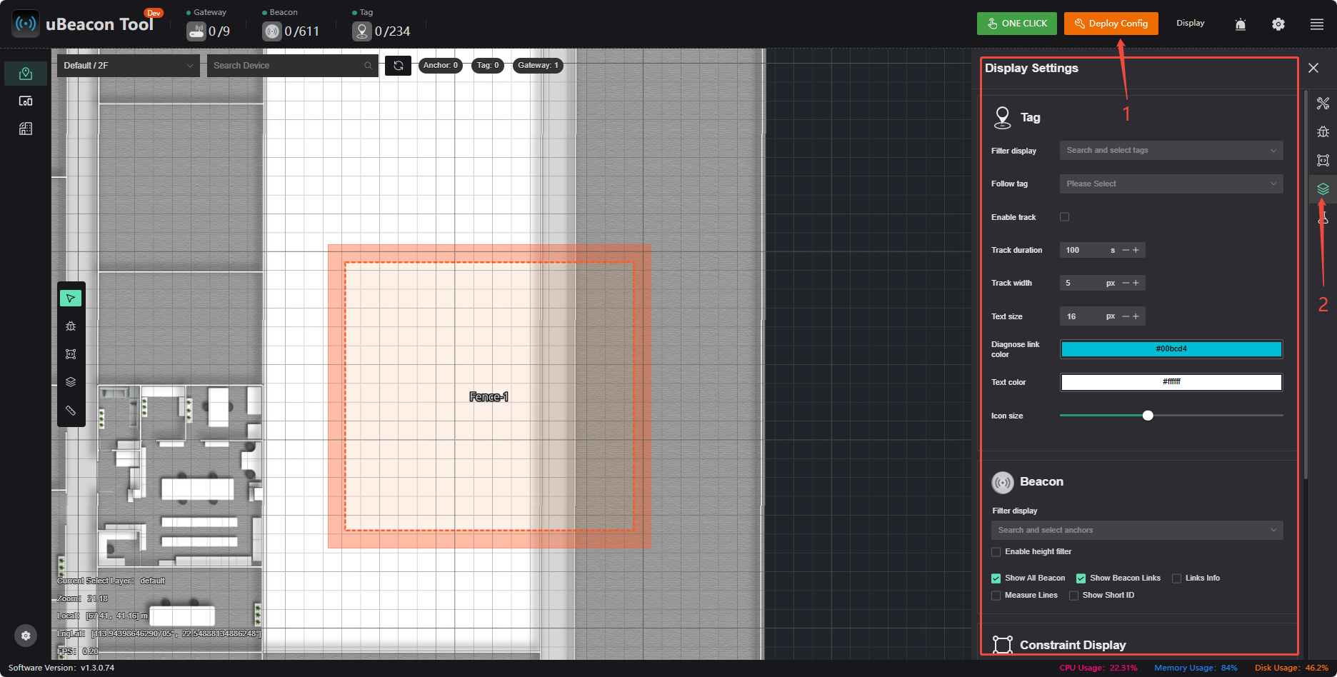
Display Settings
Filter the display of tags and beacons; choose whether to display constraints, geofences, etc.
Measure Distance