ArduPilot for TOFSense
1 Preface
Starting from July 10, 2023, theArduPilotflight control firmware begins to support the TOFSense系列products ofShenzhen Nooploop Technology Co., Ltd..Starting fromPlane/Copter/Rover 4.5, Ardupilot Firmwareadded support for the TOFSense protocol for obstacle avoidance and altitude hold. If the user uses a firmware lower than this version, they need to port and modify the relevant files themselves to support TOFSense.
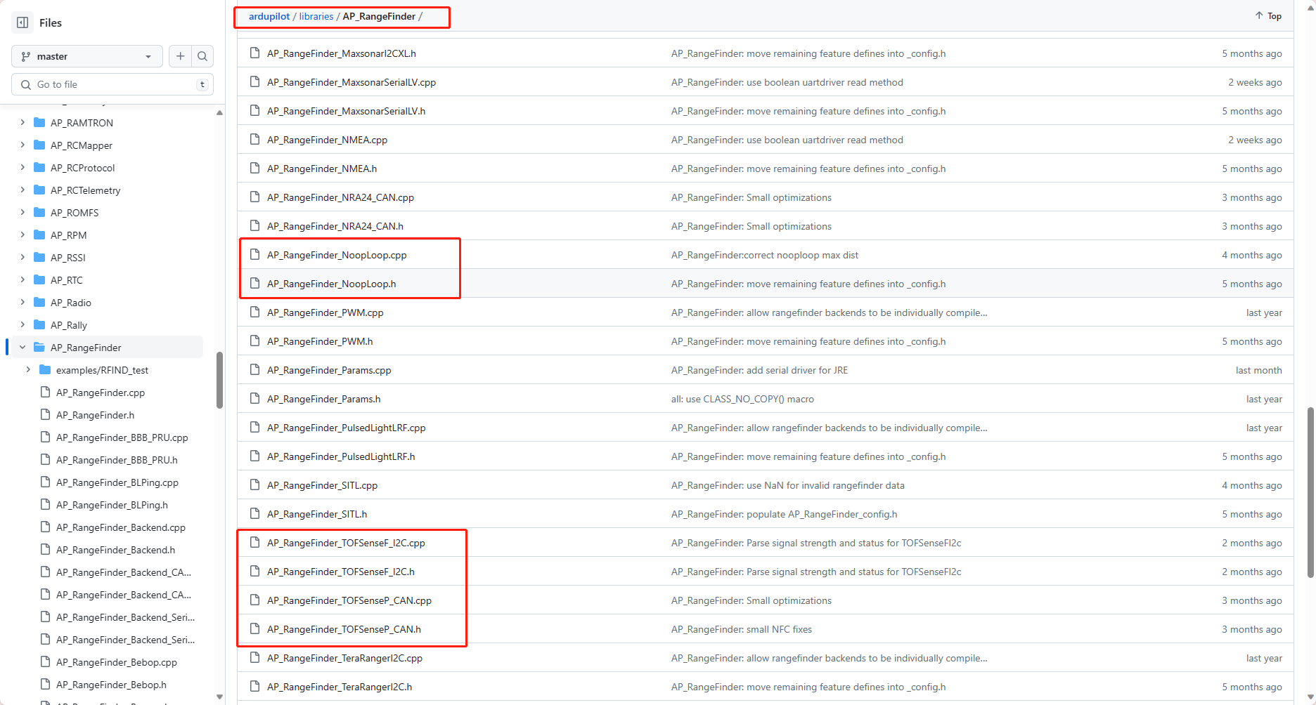
The TOFSense sensor driver file location is as follows. The porting can refer to the file changes in the following branch link according to the model and mode of the module used.
TOFSense UART Driver Branch Link
TOFSense CAN Driver Branch Link
TOFSense-F IIC Driver Branch Link
TOFSense-M LUA Script Driver Branch Link
APMGithub Source Code Link, The M series exists as a lua script and can be obtained from official technical support.
PS: The above link is a Github link. If you cannot open it, try changing the network or wait for a while before accessing it again.
2 TOFSense Series
Use Pixhawk 4Flight Controlboard as a demonstration.
2.1 UART
2.1.1 TOFSense Parameter Settings
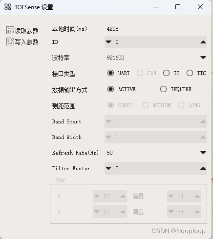
Use UART mode for communication and keep the default factory parameters. Take the settings in the following figure as an example.
2.1.2 Wiring
Users need to check the flight controller UART interface line sequence in advance and prepare a 6 to 4 pin adapter cable. Usually the flight controller will give it away, but the line sequence and terminals may not match. TOFSense needs to change the line sequence manually. The TOFSense standard interface is 4P GH1.25, and the terminals and line sequence are
| TOFSense | Flight Control Pixhawk |
|---|---|
| VCC | 5V |
| GND | GND |
| RX | TX |
| TX | RX |
The following figure takes Pixhawk 4 as an example
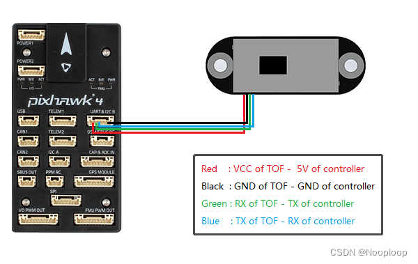
Note: The line sequence used by the flight control board interface is different from the line sequence of the TOFSense series. Users need to prepare the adapter cable in advance according to the data sheet of the flight control board. Do not connect it directly to the TOFSense, which may burn out the TOFSense.
2.1.3 Flight Control Parameter Setting
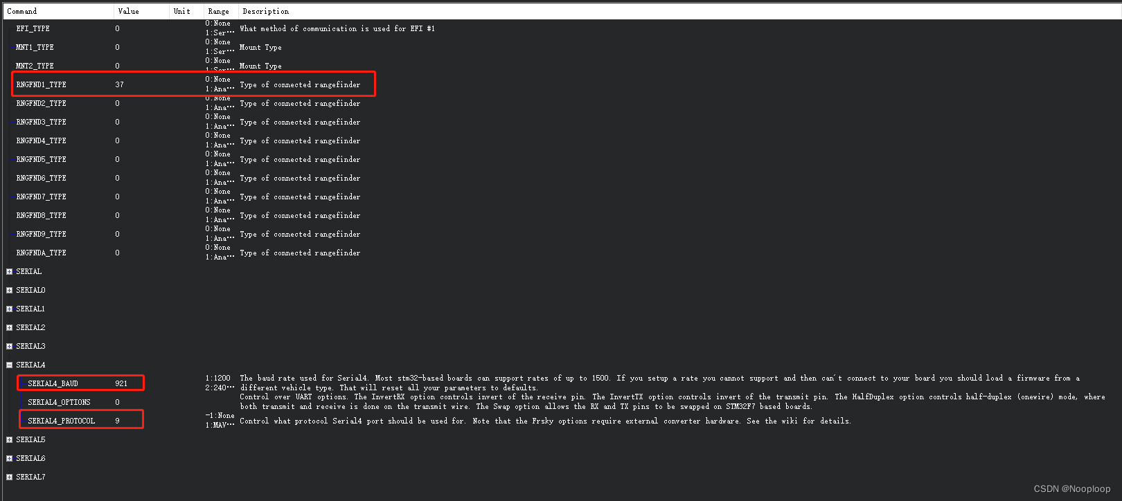
Open Mission Planner, connect to the flight controller, click Configure and Debug, click the All Parameters table on the left, search for the following parameter names in the search box on the right and change them.
SERIALx_PROTOCOL = 9
SERIALx_BAUDRATE = 921
RNGFND1_TYPE = 37
// x represents the selected serial port number
// For example, if you want to use serial port 4 to obtain data, make the following settings
SERIAL4_PROTOCOL = 9
SERIAL4_BAUD = 921
RNGFND1_TYPE = 37
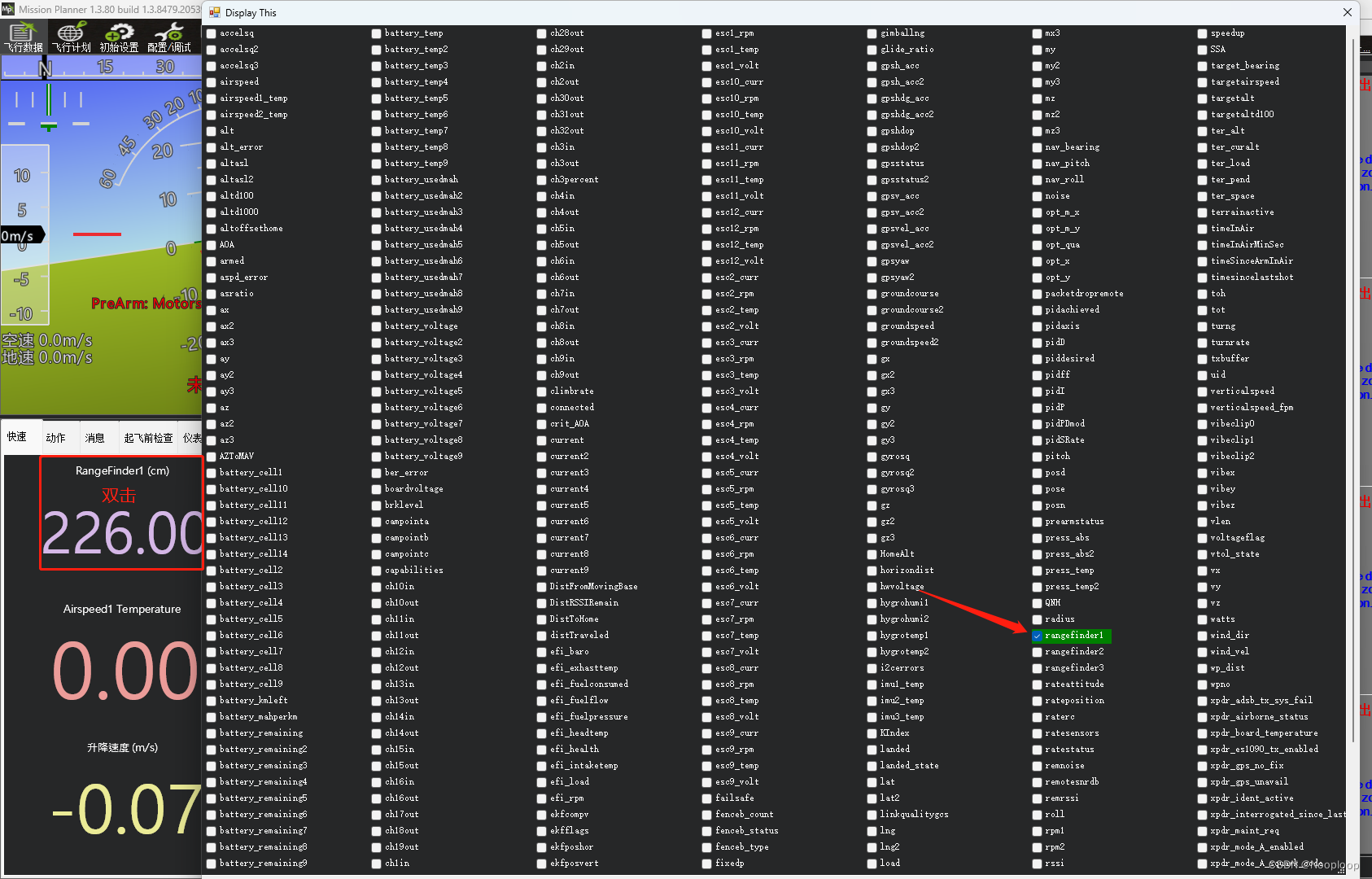
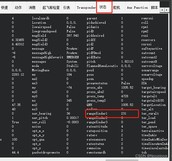
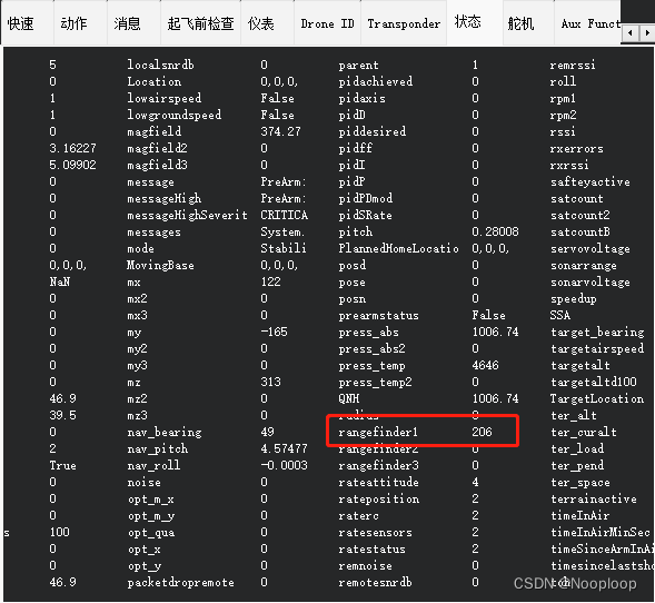
After completing the above settings, click Write Parameters on the right, then restart the flight controller. After Mission Planner reconnects to the flight controller, click the flight control data in the upper left corner, double-click on the quick page and select rangefinder1 to see the module data, or click status to find rangefinder1 to see the module data.
2.2 CAN (Supports Cascading)
Support TOFSense/P/PS and other models
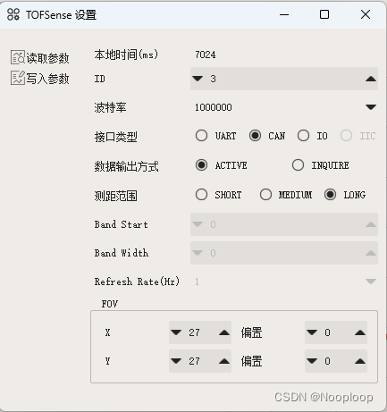
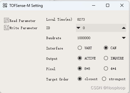
2.2.1 TOFSense Parameter Settings
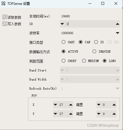
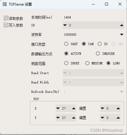
The factory default mode of TOFSense is UART mode. For CAN mode, you need to useNAssistantto change the parameters of the module. You can refer to the user manual of the corresponding model. The following example is 3 TOFSense cascaded, and the IDs are set to 1, 2, and 3 respectively.
2.2.2 Wiring
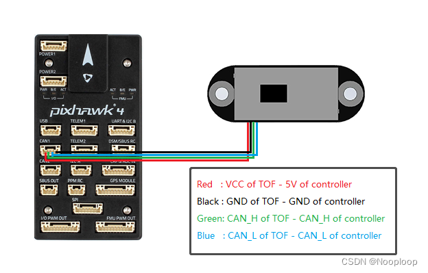
Note: The line sequence used by the flight control board CAN is different from that of the TOFSense series, so the double-headed GH1.25 data cable that comes with TOFSense cannot be directly plugged in. Users need to prepare the adapter cable in advance according to the data sheet of the flight control board. If you connect it rashly, it may cause TOFSense to burn out.
The following figure shows the definition of the CAN interface used in the test using pixhawk 4
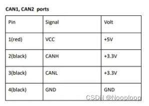
| TOFSense | Flight Control Pixhawk |
|---|---|
| VCC | 5V |
| GND | GND |
| CAN_H | CAN_H |
| CAN_L | CAN_L |
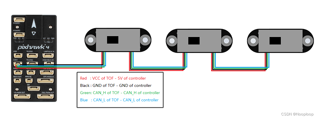
Cascade schematic diagram
2.2.3 Flight Control Parameter Setting
Open Mission Planner, connect to the flight controller, click Configuration and Debug, click the All Parameters table on the left, search for the following parameter names in the search box on the right and change them.
//CAN Configuration
CAN_P1_DRIVER = 1
CAN_P1_BITRATE = 1000000
CAN_D1_PROTOCOL = 13
The cascade parameters are configured as follows
RNGFND1/2/3/4/5_TYPE = 38
RNGFND1/2/3/4/5_RECV_ID = TOFSense模块ID

Cascading 3 Examples
RNGFND1_TYPE = 38
RNGFND1_RECV_ID = 1

RNGFND2_TYPE = 38
RNGFND2_RECV_ID = 2

RNGFND3_TYPE = 38
RNGFND3_RECV_ID = 3
PS: If you can't find CAN_P1_BITRATE, write CAN_P1_DRIVER = 1 first and then restart the flight controller to find it
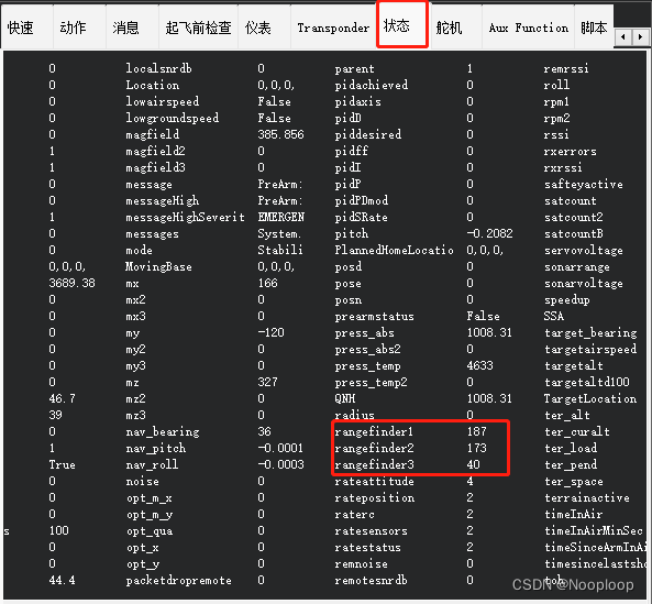
After completing the above settings, click Write Parameters on the right, then restart the flight controller. If the settings are correct, you can see that rangefinder1/2/3 is refreshed normally.

3 TOFSense-F Series
3.1 UART
Use UART mode for communication and keep the default factory parameters. Take the settings in the following figure as an example.

Other operations are the same as TOFSense settings, refer to 2.1 UART section
3.2 IIC (Support Cascading)
3.2.1 TOFSense-F IIC Parameter Settings
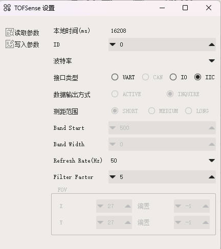
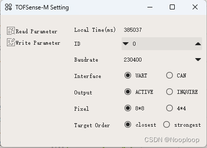
The factory default mode of TOFSense-F is UART mode. For IIC mode, you need to use NAssistantto change the module parameters. You can refer to the user manual of the corresponding model. The following example is 7 TOFSense-F IIC mode cascade, and the IDs are set to 0~6 respectively. The IDs of each module need to be remembered, which will be used later when setting the flight control parameters.
The following figure uses ID 0 parameter settings. The remaining parameters of other modules are the same except for ID.
3.2.2 Wiring
Note: The line sequence of the IIC interface of the flight control board is different from that of the TOFSense series, so the double-headed GH1.25 data cable that comes with TOFSense cannot be directly plugged in and used. Users need to prepare the adapter cable in advance according to the data sheet of the flight control board. If you act rashly, TOFSense may be burned out.
The following figure shows the test using the pixhawk 4 IIC interface definition
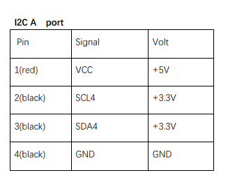
| TOFSense-F | Flight Control Pixhawk |
|---|---|
| VCC | 5V |
| GND | GND |
| SDA | SDA |
| SCL | SCL |
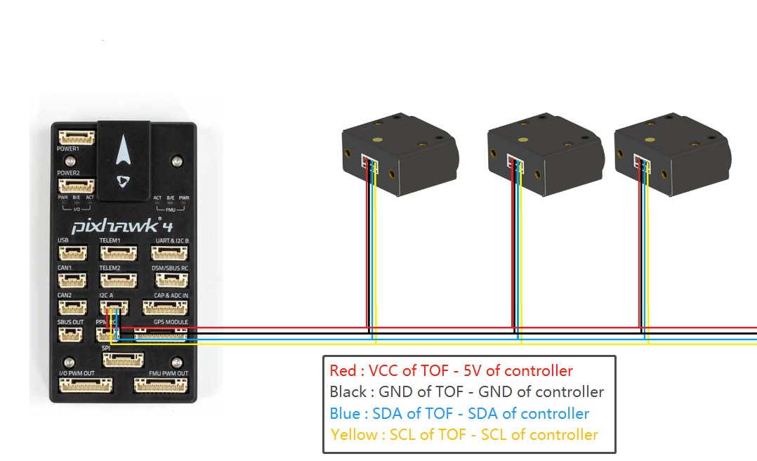
Cascade wiring diagram. TOFSense-F has only one GH1.25 interface, so the cascade connection needs to be transferred by yourself. You can refer to the following example wiring diagram
3.2.3 Flight control parameter setting and adding script files
Open Mission Planner, connect to the flight controller, click Configure and Debug, click the All Parameters table on the left, search for the following parameter names in the search box on the right and change them.
RNGFND1/2/3/4/5_TYPE = 40
RNGFND1/2/3/4/5_ADDR = TOFSense module ID + 8
Since the TOFSense-F IIC address starts from 0x08, RNGFNDx_ADDR requires module id + 0x08
// The 7 TOFSense-F IIC cascade parameters are set as follows
RNGFND1_TYPE = 40
RNGFND1_ADDR = 8

RNGFND2_TYPE = 40
RNGFND2_ADDR = 9

RNGFND3_TYPE = 40
RNGFND3_ADDR = 10

RNGFND4_TYPE = 40
RNGFND4_ADDR = 11

RNGFND5_TYPE = 40
RNGFND5_ADDR = 12

RNGFND6_TYPE = 40
RNGFND6_ADDR = 13

RNGFND7_TYPE = 40
RNGFND7_ADDR = 14
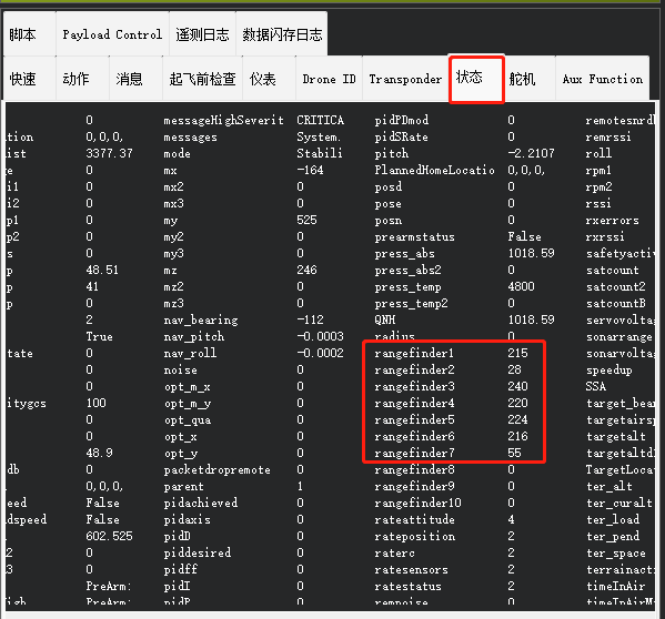
After completing the above settings, click Write Parameters on the right, then restart the flight control. If the operation is correct, you can see that rangefinder1~7 is refreshed normally.
PS: If you find that Mission Planner only has 3 rangefinders, then you need to update Mission Planner to version 1.3.81.
4 TOFSense-M Series
The TOFSense-M series is a special module developed in the form of LUA scripts, so it is not limited to the firmware version of Ardupilot. It only requires slight configuration and adding script files.
4.1 UART
Due to LUA script limitations, the baud rate of TOFSense-M must be set to 230400 for normal communication
4.1.1 Wiring
Users need to check the flight controller UART interface line sequence in advance and prepare a 6 to 4 pin adapter cable. Generally, the flight controller will give one away, but the line sequence does not match TOFSense-M. You need to manually change the line sequence. The line sequence is
| TOFSense-M | Flight Control Pixhawk |
|---|---|
| VCC | 5V |
| GND | GND |
| RX | TX |
| TX | RX |
The following figure takes Pixhawk 4 as an example

4.1.2 Flight Control Parameter Setting and Adding Script Files
It is recommended that users have a general understanding of the use of LUA scripts. You can refer to the LUA script tutorial written by Ardupolit.
Enable the script when adding it for the first time
SCR_ENABLE = 1
SCR_HEAP_SIZE = 150000
Write the parameters to restart the flight control, download the corresponding script file from the Nooploop Official Websiteor ask technical support for the corresponding script file, TOFSense-M_Serial.lua, and then upload the script file to the "scripts" folder via MP ftp.
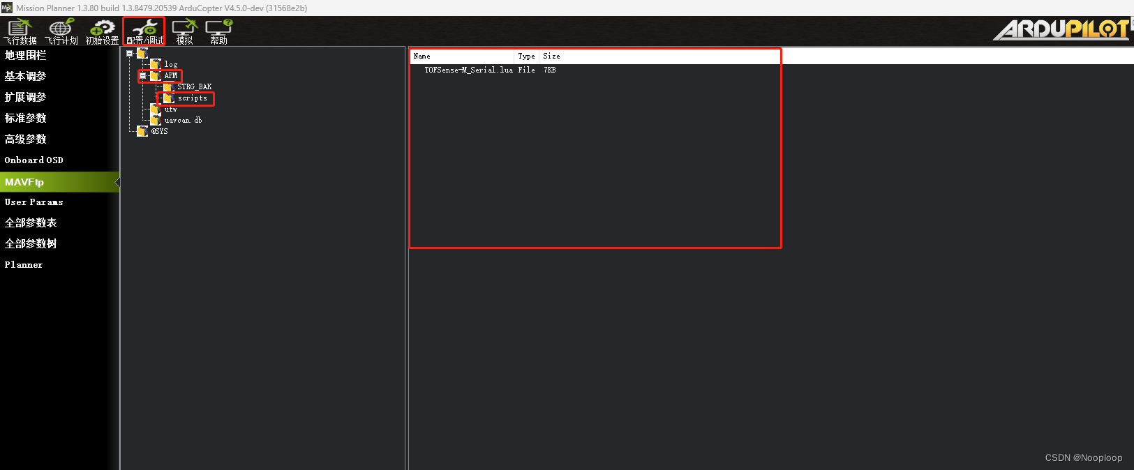
You can also use Mission Planner to upload the file, click Configuration/Debug, click MAVFtp on the left, find APM/scripts, and drag the script file to the blank space on the right to complete the upload. After successful addition, it will be displayed as shown below PS:What should I do if there is no scripts folder when I open APM?
Then set it in sequence
SERIAL4_PROTOCOL = 28
SERIAL4_BAUD = 230
Choose one of the following two settings
- Output as 1D data
This setting outputs TOFSense-M as a 1D traditional sensor. The output value is rangefider1. The output logic is to output the minimum value of the 64 pixel distances per frame.
RNGFND1_TYPE = 36
TOFSENSE_S1_PRX = 0

- Output in 3D
This setting is to output TOFSense-M as a 3D proximity sensor
PRX1_TYPE = 15
TOFSENSE_S1_PRX = 1
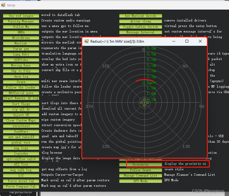
In Mission Planner, press ctrl+F to display the temp page, and find Proximity to see the module data. Ardupolit currently does not have a 3D visualization for proximity data. So what you see now is only 2D data, but in fact ArduPilot processes all data in 3D.
4.2 CAN
4.2.1 Wiring
Note: The line sequence used by the flight control board CAN is different from that of the TOFSense series, so the double-headed GH1.25 data cable that comes with TOFSense cannot be directly plugged in. Users need to prepare the adapter cable in advance according to the data sheet of the flight control board. Do not connect the TOFSense rashly, as it may burn out the TOFSense.

| TOFSense | Flight Control Pixhawk |
|---|---|
| VCC | 5V |
| GND | GND |
| CAN_H | CAN_H |
| CAN_L | CAN_L |

4.2.2 Flight control parameter setting and adding script files
It is recommended that users have a general understanding of the use of LUA scripts. You can refer to the LUA tutorial written by Ardupolit.
Enable the script when adding it for the first time
SCR_ENABLE = 1
SCR_HEAP_SIZE = 150000
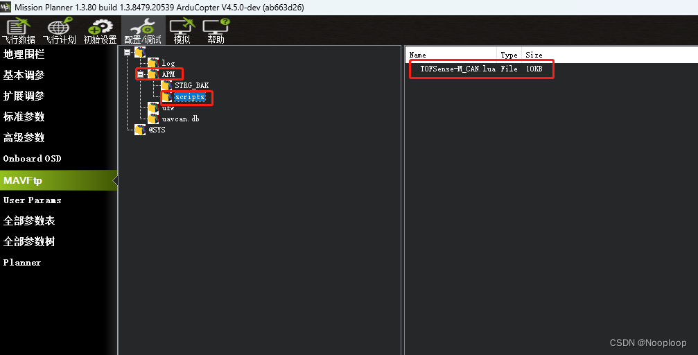
Write the parameters to restart the flight control, download the corresponding script file from the Nooploop Official Website, TOFSense-M_CAN.lua, and then upload the script file to the "scripts" folder via MP ftp. You can also use Mission Planner to upload files. Click Configuration/Debug, click MAVFtp on the left, find APM/scripts, and drag the script file to the blank space on the right to complete the upload. After successful addition, it will be displayed as shown below. PS:What should I do if there is no scripts folder when I open APM?
If the master uses CAN1 to connect to TOFSense
CAN_D1_PROTOCOL = 10
CAN_P1_DRIVER = 1

If the master uses CAN2 to connect to TOFSense
CAN_D2_PROTOCOL = 10
CAN_P2_DRIVER = 2
Choose one of the following two settings
- Output as 1D data
This setting outputs TOFSense-M as a 1D traditional sensor. The output value is rangefider1. The output logic is to output the minimum value of the 64 pixel distances per frame.
RNGFND1_TYPE = 36
TOFSENSE_PRX = 0
- Output in 3D This setting is to output TOFSense-M as a 3D proximity sensor
PRX1_TYPE = 15
TOFSENSE_PRX = 1
In Mission Planner, press ctrl+F to display the temp page, and find Proximity to see the module data. Ardupolit currently does not have a 3D visualization for proximity data. So what you see now is only 2D data, but in fact ArduPilot processes all data in 3D.
