FAQ-TOFSense
1 FAQ
Q1. Can it be used outdoors?
A: It can be used outdoors, but the module range will be affected by natural light. Generally speaking, the stronger the natural light, the greater the impact, which manifests as a shorter ranging range.
Q2. Will there be interference when multiple modules work at the same time?
A: When multiple modules are working at the same time, even if the infrared rays of each other cross or hit the same position, it will not affect the actual measurement. If two modules are at the same level and facing each other, the measurement will affect both.
Q3. Why is there no data output from the module?
A: Each module is shipped after strict testing. If there is no data, please check the mode, wiring (whether the power supply voltage and line sequence are correct, and it is recommended to use a multimeter to test whether the pins at both ends of the communication are conductive), baud rate and other configurations. For CAN output mode, please check whether it contains terminal resistance (usually 120Ω). For IIC output mode, the host needs to use IIC communication to read data from the set slave address according to the communication timing in the manual.
Q4. Does the reflectivity of the surface of an object affect the sensor?
A: In actual use, the range and accuracy of the sensor may be affected by the reflectivity of the object being measured. Under the same environment, the measurement results may be different for objects with different reflectivity. Therefore, when using the sensor, it is recommended that users conduct sufficient tests in actual scenes, and calibrate for specific scenes if more accurate measurement results are required. It is recommended to compare the test data of the cardboard and the actual object being measured, and analyze, compensate and optimize according to the signal strength.
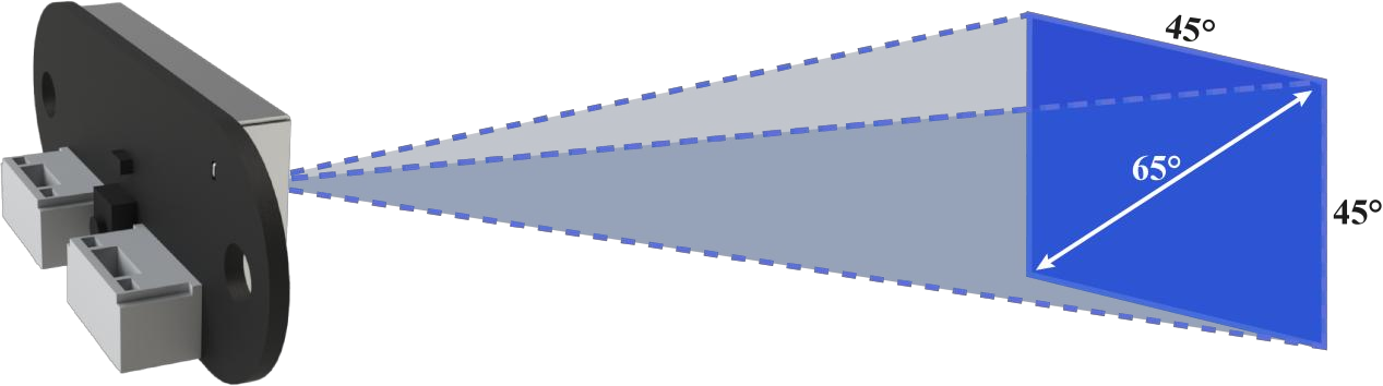
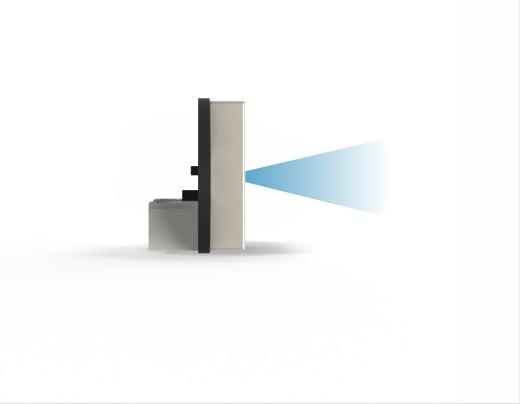
Q5. What is the FOV of the TOFSense-M series modules?
A: The field of view of the TOFSense-M series module is 45° horizontally and vertically, with a maximum diagonal angle of 65°. As shown in the figure below, the FOV area of the TOFSense-M series is a quadrangular pyramid with a square bottom and a vertex at the emission window. When facing a sufficiently large object, the side length of the square range covered by its FOV on the measured plane can be estimated by trigonometric function R = L * tan45° (L: the distance between the TOFSense-M series module and the measured object).
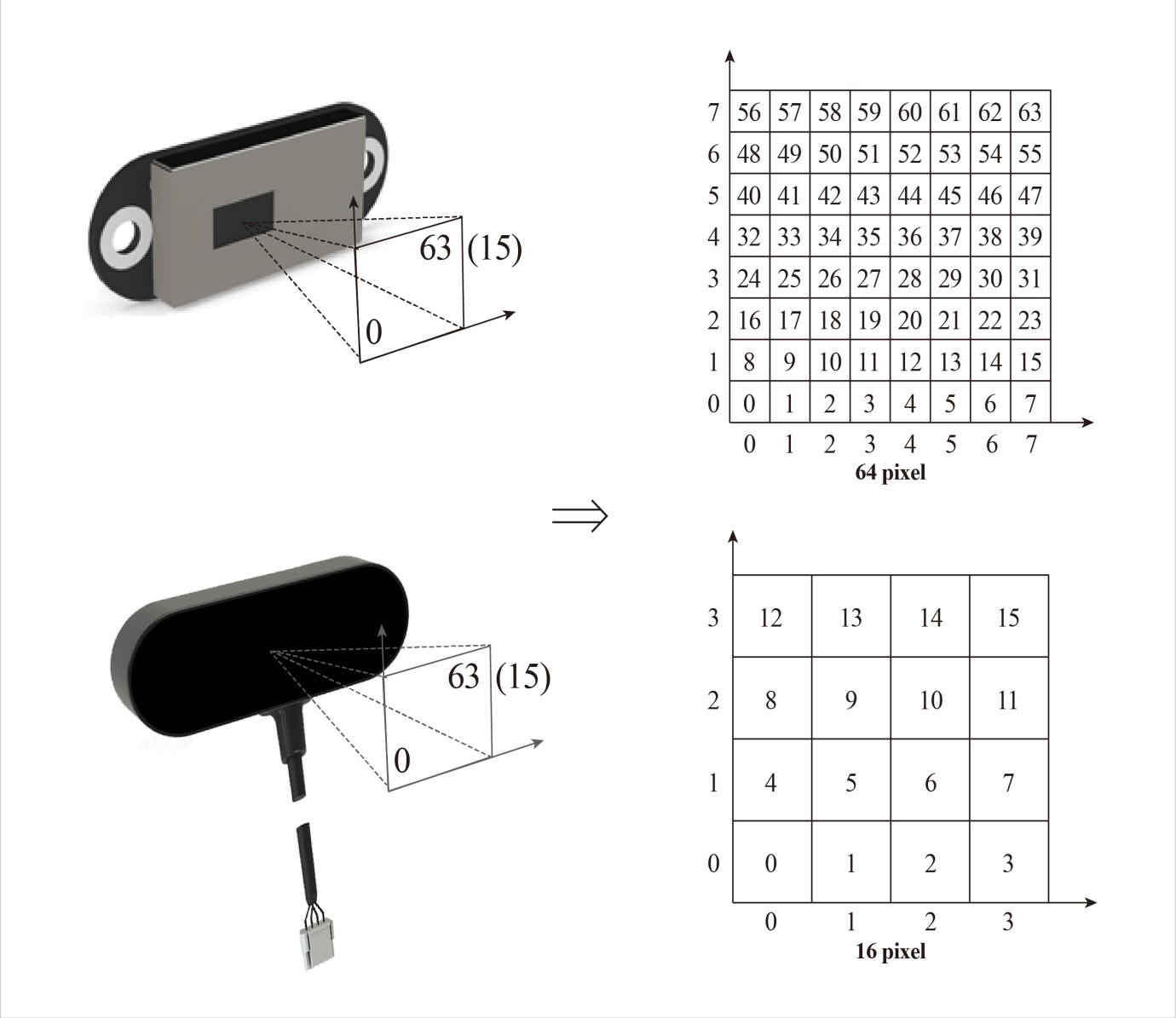
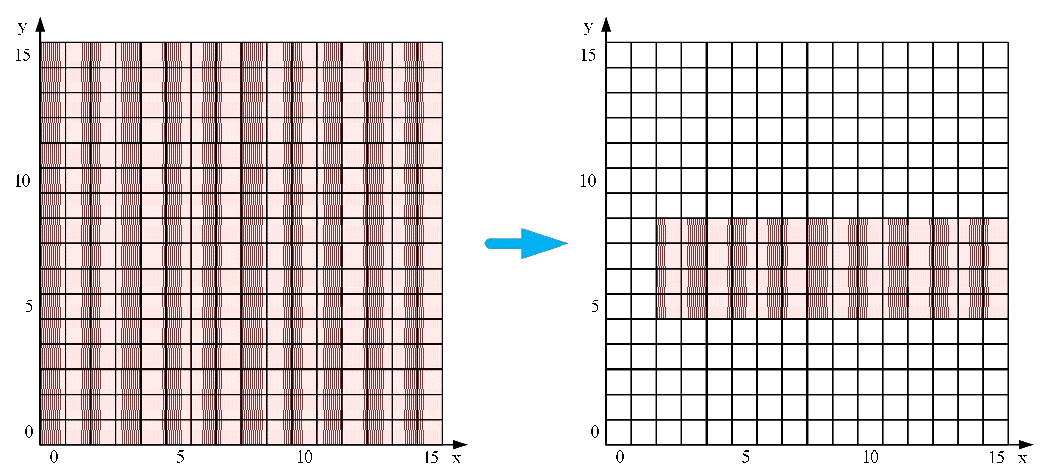
TOFSense-M series modules support 64 (8x8) and 16 (4x4) pixel outputs. The relationship between pixels and actual output is shown in the figure below.
Q6. What is the FOV of the TOFSense-F2 series modules?
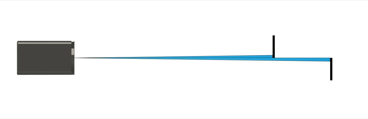
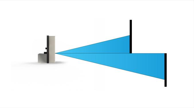
A: The field of view of the TOFSense-F2 P/TOFSense-F2 PH module is 1-2°, and the field of view of the TOFSense-F2 Mini module is 2-3°. The FOV area of the TOFSense-F2 series is a cone with a round bottom and a vertex at the emission window. Taking a 2° field of view as an example, when facing a large enough object, the diameter of the circular range covered by its FOV on the measured plane can be estimated by trigonometric function R = L * tan2° (L: the distance between the TOFSense-F2 series module and the measured object). When there are multiple objects to be measured within the module FOV range at the same time, as shown in the figure below, the output measurement value will be abnormal. If high accuracy is required during use, such situations should be avoided as much as possible to reduce measurement errors.
Q7. What is the FOV of the TOFSense series modules?
A: The FOV area of the TOFSense series module is a cone with a circular bottom and its apex at the emission window. Taking a 27° field of view as an example, when facing a sufficiently large object, the diameter of the circular range covered by its FOV on the measured plane can be estimated by trigonometric function R = L * tan27° (L: the distance between the TOFSense module and the object being measured).
The initial FOV parameters of the module are fov.x=27°, fov.y=27°, fov.x_offset=0°, fov.y_offset=0°. You can change the module's area of interest to the right side of the figure below by setting the X-direction field of view to 25° (corresponding to the bottom view), the Y-direction field of view to 15° (corresponding to the side view), the X-direction offset to 1°, and the Y-direction offset to -1°.
When there are multiple objects to be measured within the module's FOV, as shown in the figure below, the output measurement value will be abnormal. If high accuracy is required during use, such situations should be avoided as much as possible to reduce measurement errors.
A smaller FOV can improve the module's detection performance in narrow spaces and small objects, but changes in the FOV field of view will also affect the module's maximum ranging distance. The smaller the field of view angle, the smaller the maximum ranging distance.
Q8. What should I pay attention to during installation?
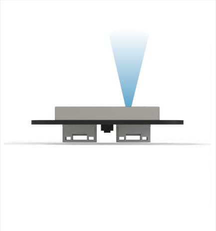
A: If you do not want to detect the ground or other reflective surfaces, avoid obstructions in the FOV angle during installation. Also, pay attention to the height from the ground. Avoid ground obstructions and other similar reflective surfaces in the FOV. If the installation height is close to the ground, consider installing the module slightly tilted upwards.
Q9. Do the module's UART, IIC, CAN and I/O protocols share the same interface?
A: Yes, the module's UART, IIC, CAN, and I/O protocol interfaces share the same physical interface. You only need to convert the corresponding line sequence for different communication modes. Note that the protocols supported by each module model are different. The TOFSense series supports UART, CAN, and I/O protocols, the TOFSense-F2 series supports UART, IIC, and I/O protocols, and the TOFSense-M series supports UART and CAN protocols.
Q10. Why can't NAssistant recognize the TOFSense-M series module after it switches to CAN mode? How can I switch between different communication modes?
A: Currently, NAssistant software only supports identifying modules in UART mode. In UART mode, after successful identification by the host computer, enter the setting page to configure the module to CAN communication mode; In CAN communication mode, TOFSense-M needs to press and hold the button and then power on the module. When the indicator light changes from fast flashing to slow flashing, release the button. At this time, the module is forced to enter temporary UART mode. Then enter the setting page through the host computer and select UART mode to write parameters. TOFSense-M S can switch back to UART mode by sending the following serial port command to the module several times: 54 20 00 ff 00 ff ff ff 00 ff ff 00 10 0e ff ff ff ff ff ff ff ff ff ff ff ff ff ff ff ff ff ff 7b
Q11. Why can't the NAssistant software recognize the TOFSense-F2 series module after it switches to IIC or I/O mode? How can I switch between different communication modes?
A: Currently, NAssistant software only supports the identification of modules in UART mode. In UART mode, you can enter the setting page to configure the module to IIC or I/O communication mode after the host computer successfully identifies it; In IIC communication mode, you can send instructions to the module through IIC communication according to the IIC communication protocol to switch back to UART or I/O mode; In the absence of IIC test environment or after switching to I/O mode, you can switch back to UART mode in the following ways:
-
The user needs to prepare a USB to TTL module (CP2102 is recommended) that supports a baud rate of 921600 and install the corresponding driver. Connect the TX, RX, and 5V wires of the USB to TTL module to the corresponding pins of the TOF module. Leave the GND pin unconnected for now. Then insert the USB to TTL module into the computer.
-
Open NAssistant software and click

icon to enter the serial port debugging assistant, change the baud rate to 921600, select the COM port corresponding to the USB to TTL module and click

Click the Connect button to connect the COM port (it will connect automatically in most cases), enter 54 20 00 ff 00 ff ff ff ff 00 ff ff 00 10 0e ff ff ff ff ff ff ff ff ff ff ff 00 ff ff ff 7c in the Single Send text box, change the sending interval to 20ms in the Scheduled Send column in the lower right corner, and then check Scheduled Send.
- At this time, connect the GND of the USB to TTL module to the GND pin of the TOF module. The module will switch to UART mode and start to output data. At this time, uncheck the Timed Send button, unplug the USB to TTL module, power on the module again, and click

Click the Identify button to identify the module.
If the switch fails, unplug the USB to TTL module and repeat the whole process. Do not plug and unplug the GND pin multiple times when sending commands. If the module can be recognized normally but the serial port output data is abnormal, you can manually change to UART mode in the settings page.
Q12. Why can't the NAssistant software recognize the TOFSense series module after it switches to CAN or IO mode? How can I switch between different communication modes?
A: Currently, NAssistant software only supports identifying modules in UART mode. In UART mode, after successful identification by the host computer, enter the settings page to configure the module to CAN communication mode; In CAN or IO communication mode, you need to press and hold the button and then power on the module. When the indicator light changes from fast flashing to slow flashing, release the button. At this time, the module is forced to enter temporary UART mode. Then enter the settings page through the host computer and select UART mode to write parameters.
Q13. Does the module support output of point cloud information?
A: TOFSense series/TOFSense-F2 series modules can only output one distance data at a time and do not support the output of point cloud information. TOFSense-M series modules can output 64 points (8x8) or 16 points (4x4) distance data at a time.
Q14. What is the serial communication terminal model used by the module? What should I do if there is no interface for this terminal on the flight control or microcontroller?
A: The module uses GH1.25 terminals. You can purchase a GH1.25 to other terminal adapter cable, or cut the GH1.25-GH1.25 cable that comes with the product and solder other terminals yourself. Please refer to the data sheet for the line sequence, power supply voltage, signal line level, etc.
Q15. How is the checksum in the UART protocol calculated?
A: The checksum is the sum of all the previous bytes and then the lowest byte. For example, the checksum of 55 01 00 ef 03 is 0x55+0x01+0x00+0xef+0x03=0x0148. The checksum is 48, so the complete data of this frame is 55 01 00 ef 03 48.
Q16. After CAN mode cascading, the subsequent modules cannot receive data/the data is incomplete?
A: There will be voltage drop in cascaded modules, so one line is usually used to connect all modules in series. The voltage obtained by the modules at the end is smaller. If the voltage obtained by the modules at the end is less than the minimum working voltage required in CAN mode, data will not be received or the data will be incomplete. At this time, optimization can be carried out in two aspects.
-
Increase the output power of the power supply.
-
Use the star power supply method. For example, if 7 modules need to be cascaded, first divide the power supply into 4 outputs. The first output is connected to VCC and GND of No. 1 and No. 2, the second output is connected to VCC and GND of No. 3 and No. 4, the third output is connected to VCC and GND of No. 5 and No. 6, and the fourth output is connected to VCC and GND of No. 7. Then, connect the CAN_H and CAN_L of the 7 modules in series and connect them to the CAN bus. After testing, it is the most stable to connect 2 modules to each power supply. If it is a short-term test, 3 modules can be connected to each power supply.
Q17. Can a lens be added to the laser ranging module?
A: It is not recommended to add a lens, because the transmittance or reflection of the lens may affect the ranging accuracy or range of the module. If you must add a lens, the installation position of the lens needs to be very close to the module, and the transmittance of the lens must be high enough, reaching more than 90%.
Q18. What do the distance status values of each series of modules represent?
A:
TOFSense-M Series Modules:
| Dis_status Value | Note |
|---|---|
| 0 | Measurement data available |
| 1 | Signal strength is too low |
| 2 | Phase goals |
| 3 | Target noise is overestimated |
| 4 | Target consistency check failed |
| 5 | Measurement data not updated |
| 6 | No wraparound is performed (usually the first measurement) |
| 7 | Inconsistent rate |
| 8 | The current target signal strength is low |
| 9 | Large pulse effective range (probably due to merged targets) |
| 10 | Measurement data is available, but the object was not detected in the previous inspection |
| 11 | Inconsistent measurement results |
| 12 | The target is blurred |
| 13 | The target is detected but the data is inconsistent, usually occurs when a secondary target is present |
| 255 | No target detected |
TOFSense-F2 Series Modules:
| Dis_status Value | Note |
|---|---|
| 0 | Invalid distance measurement |
| 1 | Measuring distance effective |
TOFSense series modules:
| Dis_status Value | Note |
|---|---|
| 0 | Measuring distance effective |
| 1 | Standard deviation greater than 15mm |
| 2 | Signal strength is less than 1Mcps |
| 3 | Distance below threshold |
| 4 | Phase out of bounds |
| 7 | Phase mismatch |
| 9 | Signal below crosstalk threshold |
| 11 | Multiple target distances |
| 12 | Weak signal strength |
| 14 | Invalid distance measurement |
| 255 | No target detected |