Software Deployment
After installing the IPS hardware, you need to deploy the IPS software. This document explains the deployment software for IPS using Windows as an example.
1 Dependency Installation
Please install before running the software: Microsoft Visual C++ Redistributable Version
Download link for the 64-bit operating system: https://aka.ms/vs/17/release/vc_redist.x64.exe
Download link for the 32-bit operating system: https://aka.ms/vs/17/release/vc_redist.x86.exe
Download link for the latest dependency programs: Latest supported Visual C++ Redistributable downloads | Microsoft Learn
2 Software Activation
-
Connect the server to the IPS network.
-
Change the computer's IP address to 192.168.xx.254 (default target address for the anchor is 192.168.xx.254).
-
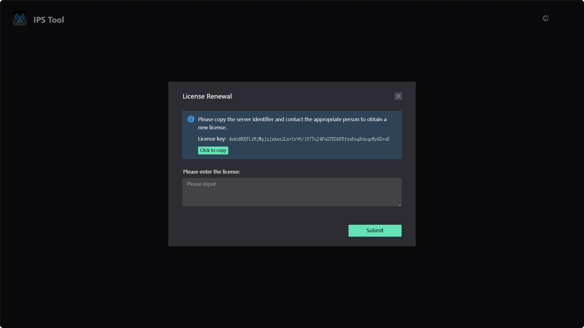
Click on the IPS Tool.exe software, which will automatically open in the default browser, leading to the following interface.Please ensure that the installation path of the software does not contain any Chinese characters or spaces.
-
Click the “Click to copy” button to send the identification code after "License key:" to Nooploop.
-
Nooploop will return the corresponding license string to the user.
-
Enter the received license string into the license box below and click “Submit” to complete the software activation.
3 Map Configuration
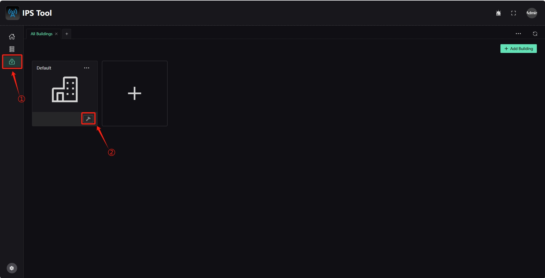
Click the “Map Management” icon in the left sidebar and select “Edit Map” from the Default box.
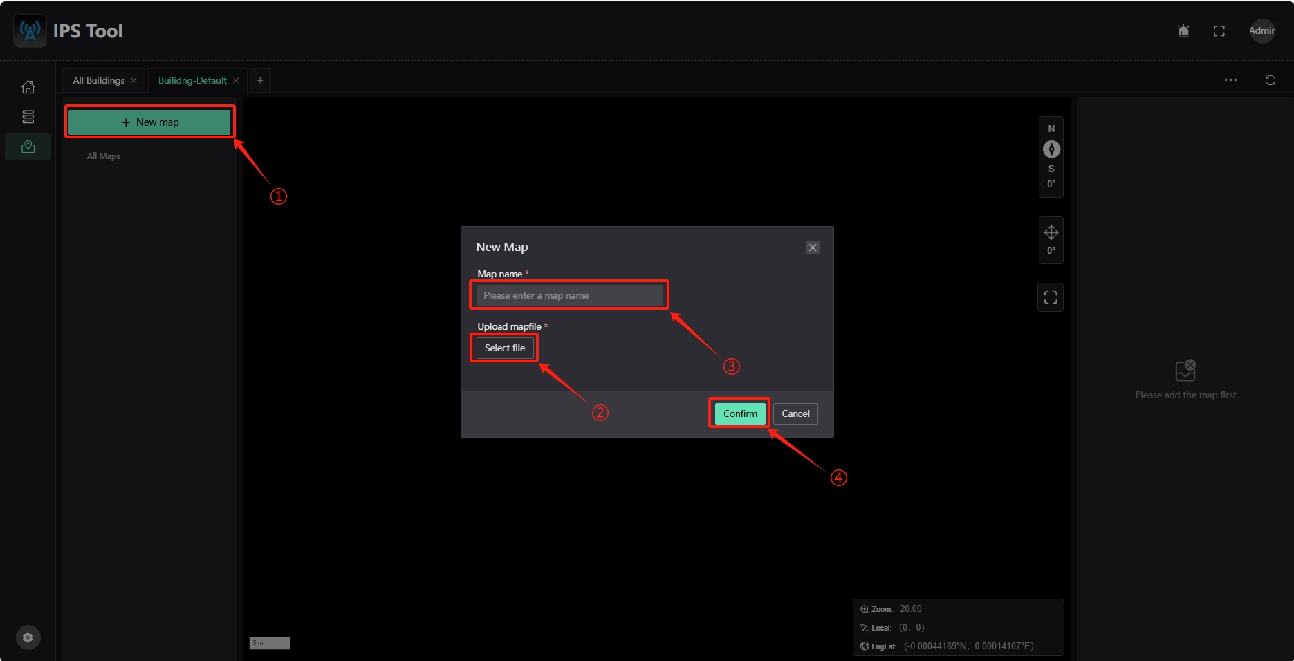
Click “+ New map,” select the map file to add (JPG or PNG format), enter the map name, and click “Confirm.”
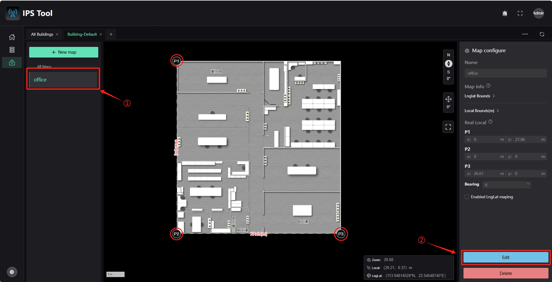
Click the newly added map name under ALL Maps to view it. The map interface will display three reference points: “P1,” “P2,” and “P3.” Configure these reference points' actual locations to map the map coordinates. Click the “Edit” button on the right to enter edit mode.
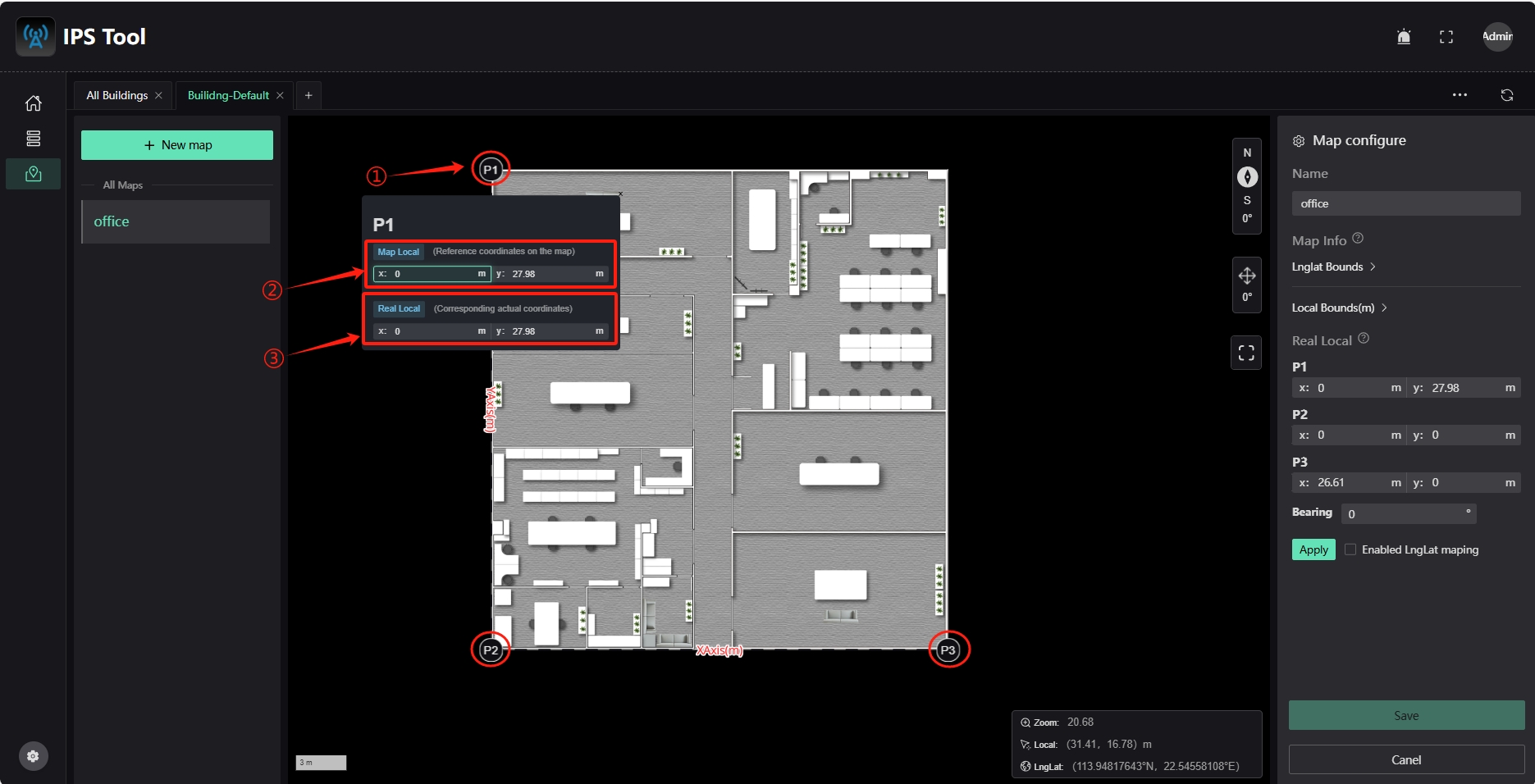
Click the reference point “P1” to view its current coordinates “Map Local” (coordinates on the map) and actual coordinates “Real Local” (actual position coordinates).
-
Move the reference point to the corresponding position on the map by dragging the reference point icon or modifying the coordinates in the “Map Local” box.
-
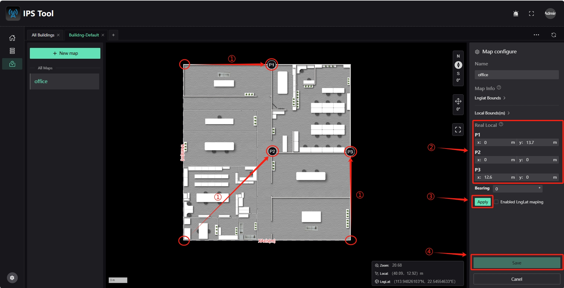
Enter the measured coordinates of each reference point in the “Real Local” input box.
-
Click the “Apply” button to complete the map coordinate mapping.
-
Click the “Save” button to save the map settings.
4 Anchor Configuration
Add Anchor
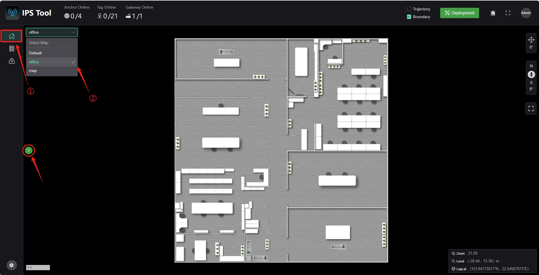
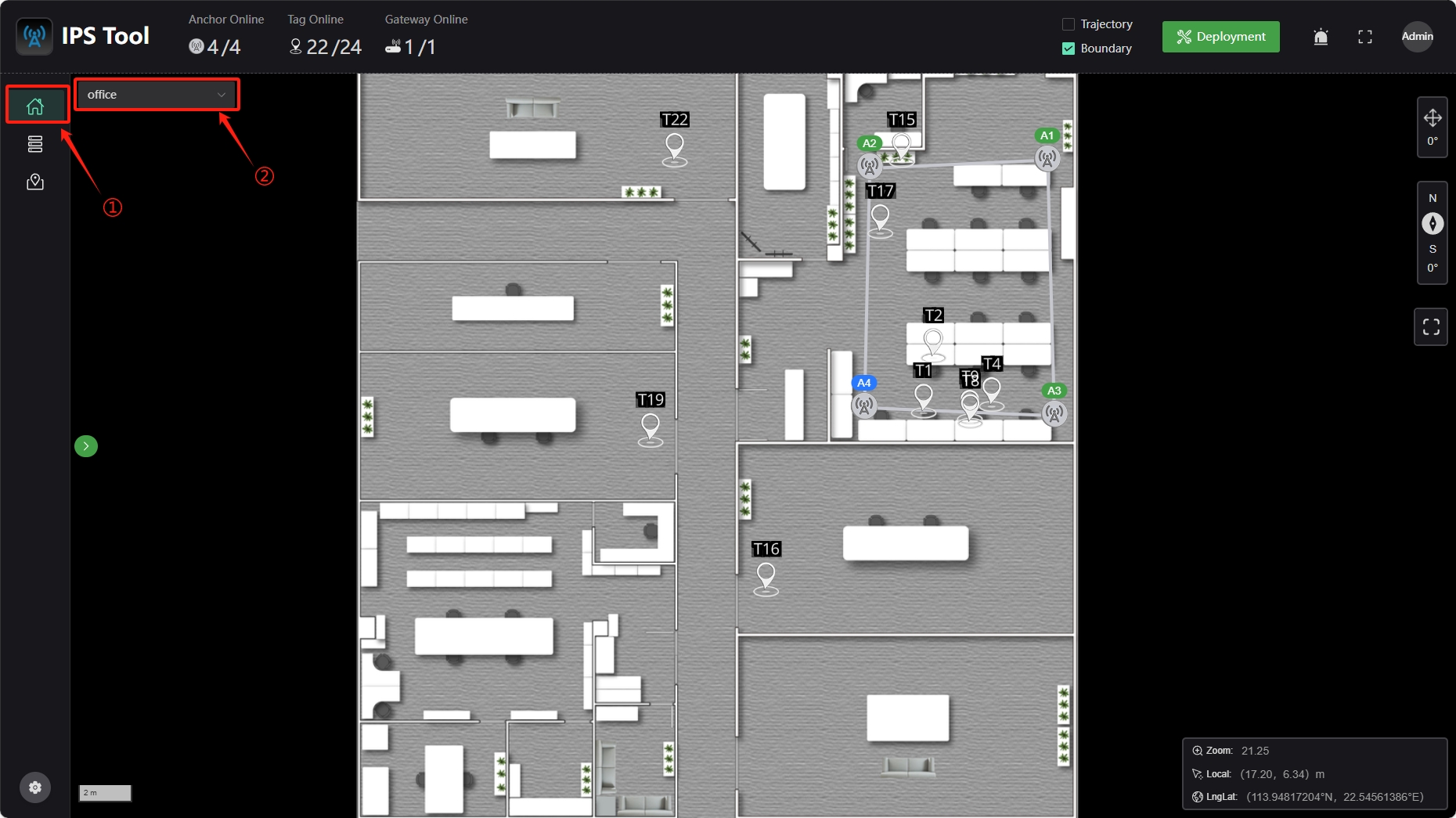
Click the “Dashboard” icon in the left sidebar, select “Select Map” from the menu, and choose the map where you want to add anchors. If the target map is not in the current building, click the “>” icon on the left to switch buildings and then select.
Click the “Deployment” icon,a menu will appear on the right. Click “Location Setup,” and you will see the anchor list under “Search for select anchor,” with red indicating offline and green indicating online.
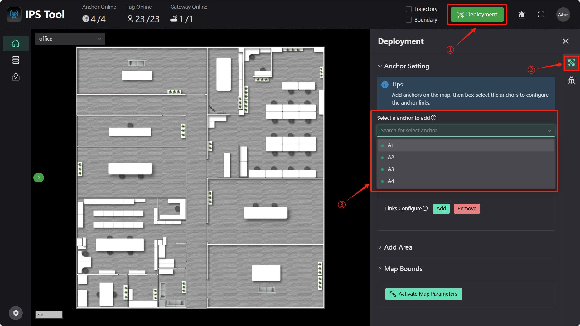
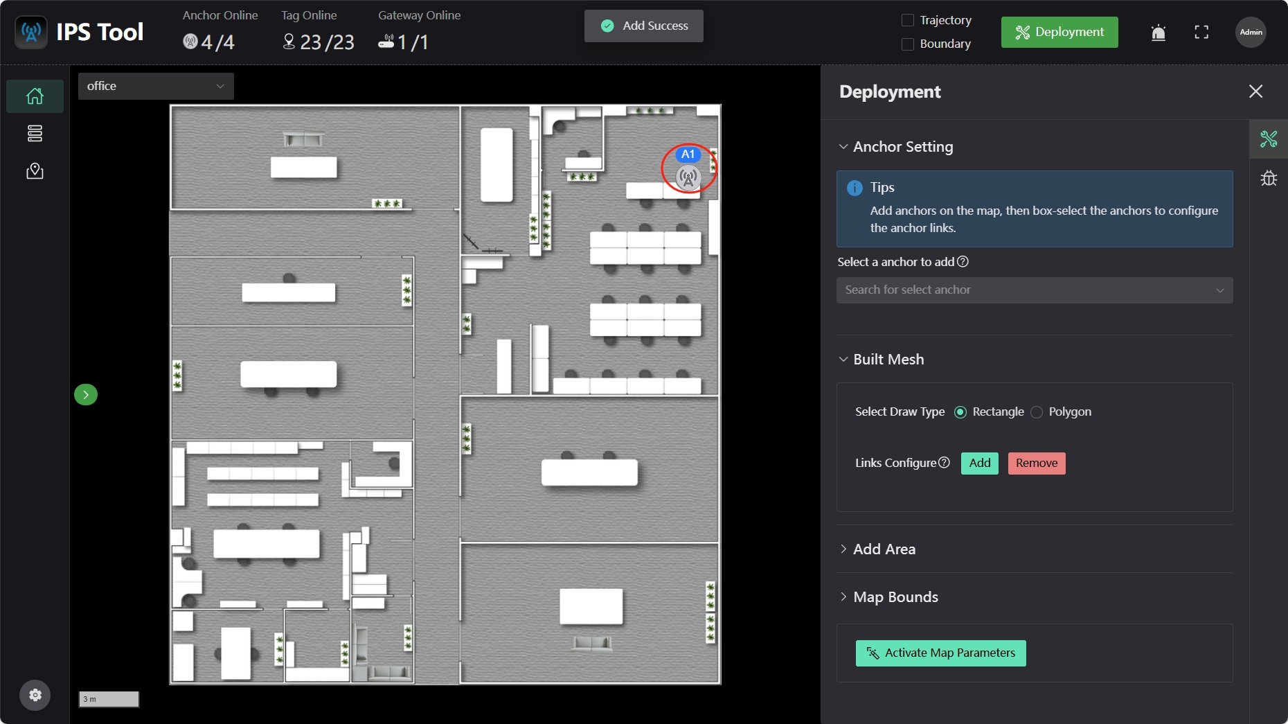
Select the anchor you want to add; the cursor will turn into a cross. Move the cursor to the corresponding map location and click the left mouse button to add the anchor.
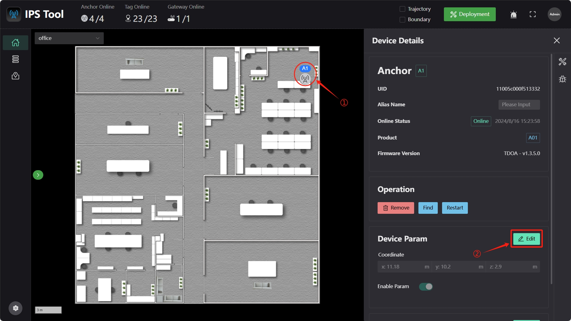
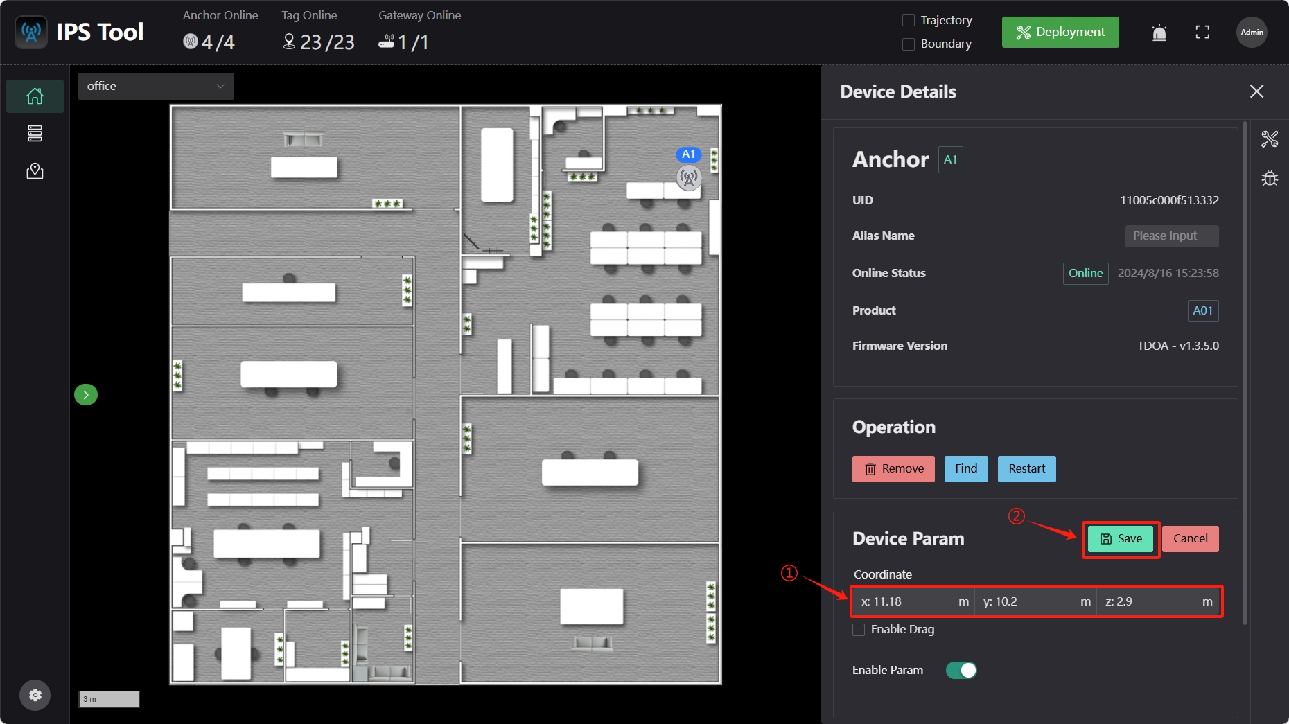
Clicking the anchor icon will pop up a anchor device information box. Click “Edit” to adjust the anchor coordinates, and click “Save” to save the anchor location information to the server.
5 Area Configuration
2D Area Positioning
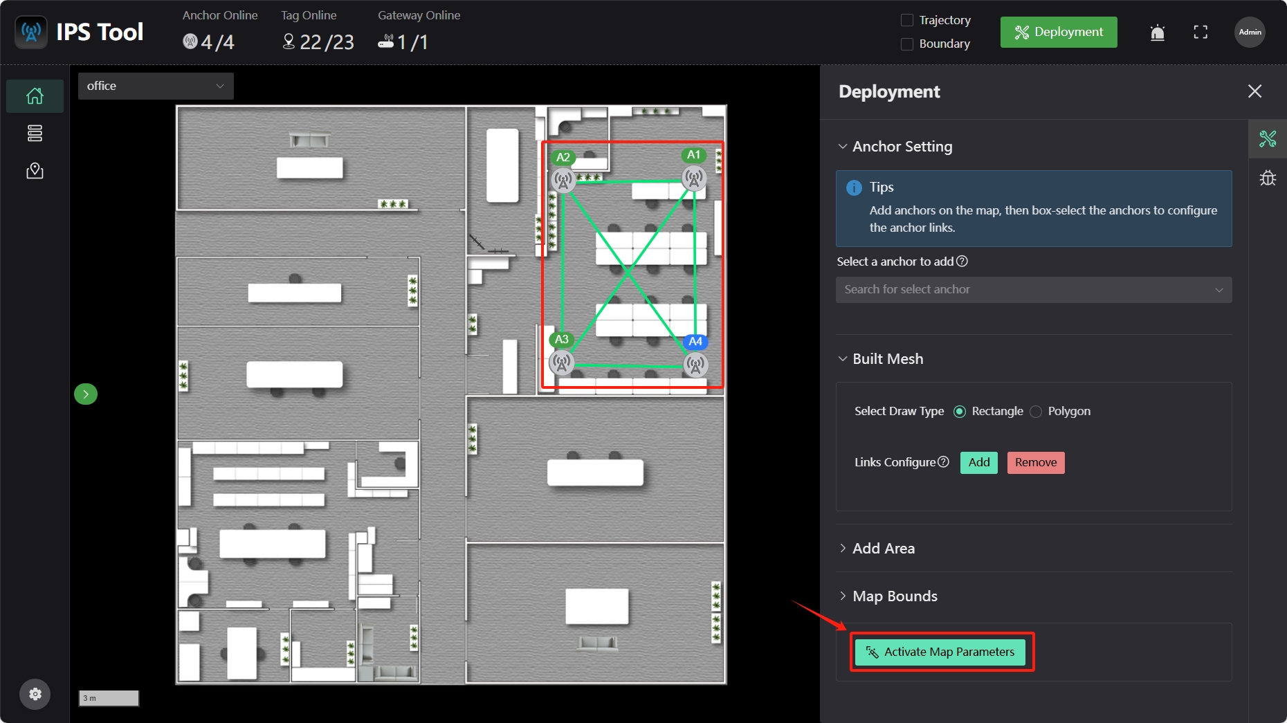
After adding all anchors, return to the “Deployment” interface, click the “Add” button in “Built Mesh,” and draw a box around all anchors that need clock synchronization in a positioning area.
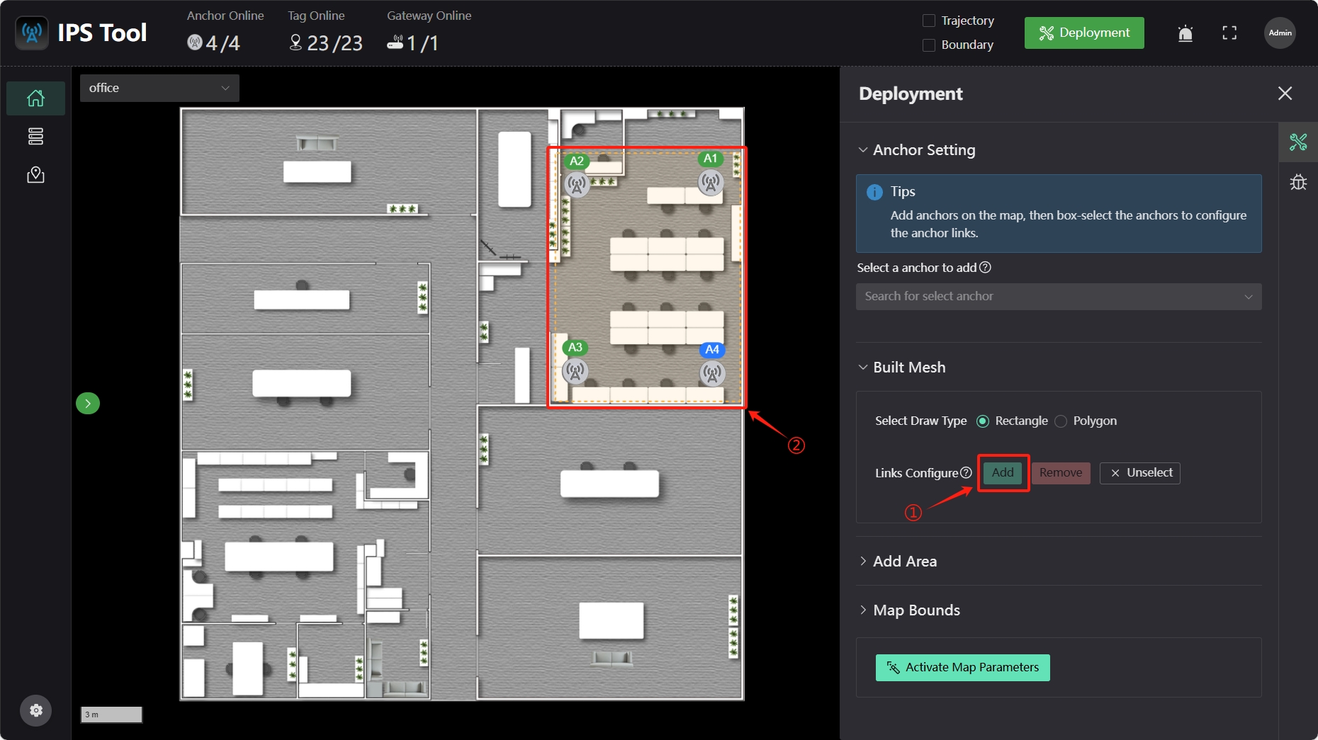
The anchors will automatically establish link connections and synchronize clocks within the area. Click the “Activate Map Parameters” button in the lower right to save the data and complete the area addition.
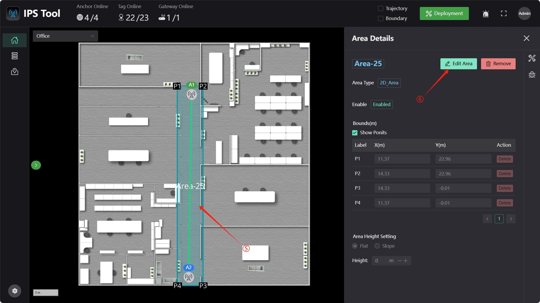
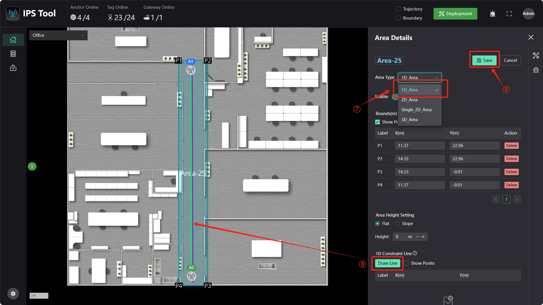
1D Area Positioning
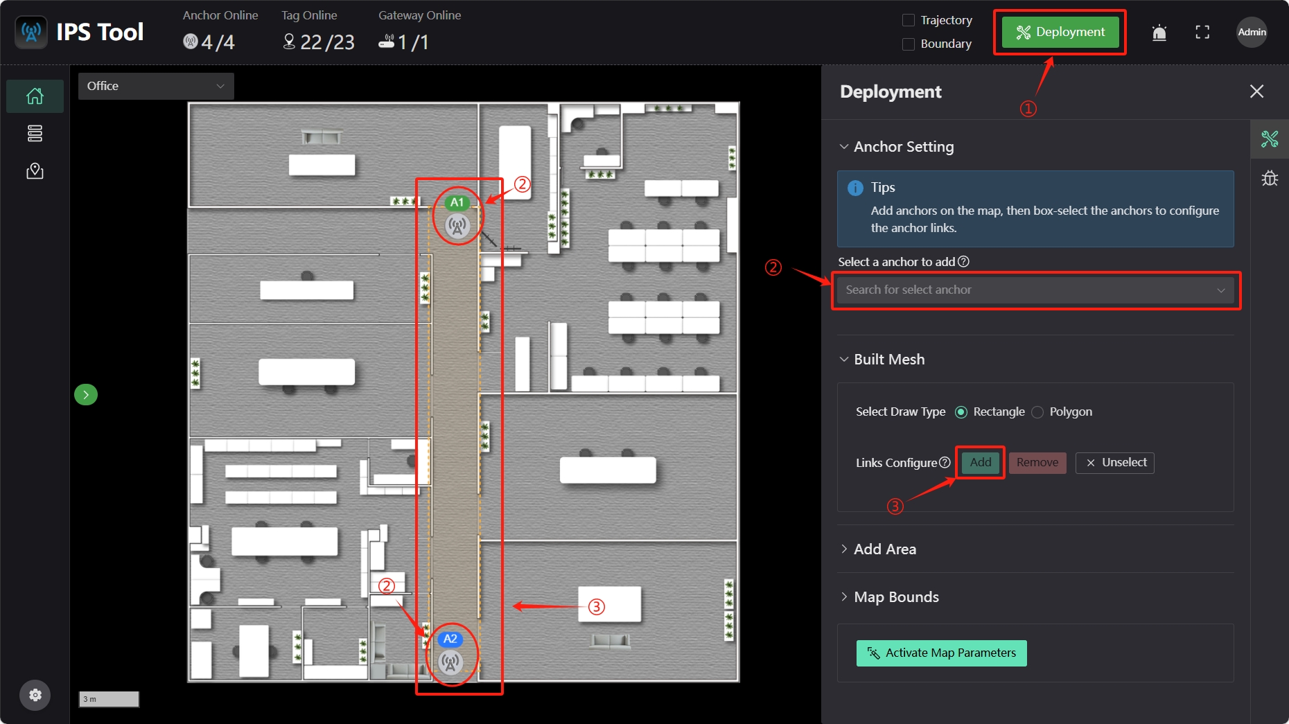
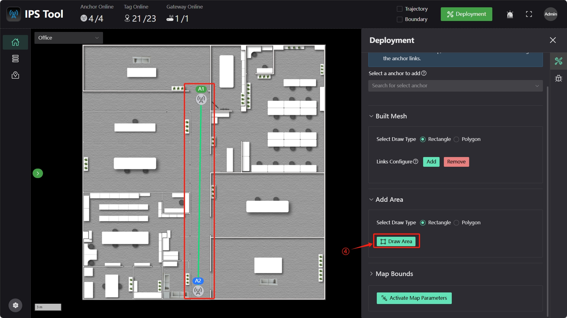
First click “Deployment” and add anchors. After setting up anchor parameters, establish communication links between anchors. Then, draw a 1D positioning area on the map, set the area type to “1D_Area,” draw a 1D constraint line (which restricts the positioning result to near this line; the “1D Constraint Std” parameter indicates the positioning result's deviation around the line), and click the “Save” button to save the settings.
6 Tag Configuration
In the “Dashboard” interface map, click a tag, and the “Device Details” menu will appear on the right. Click the “Edit” button to set tag parameters.
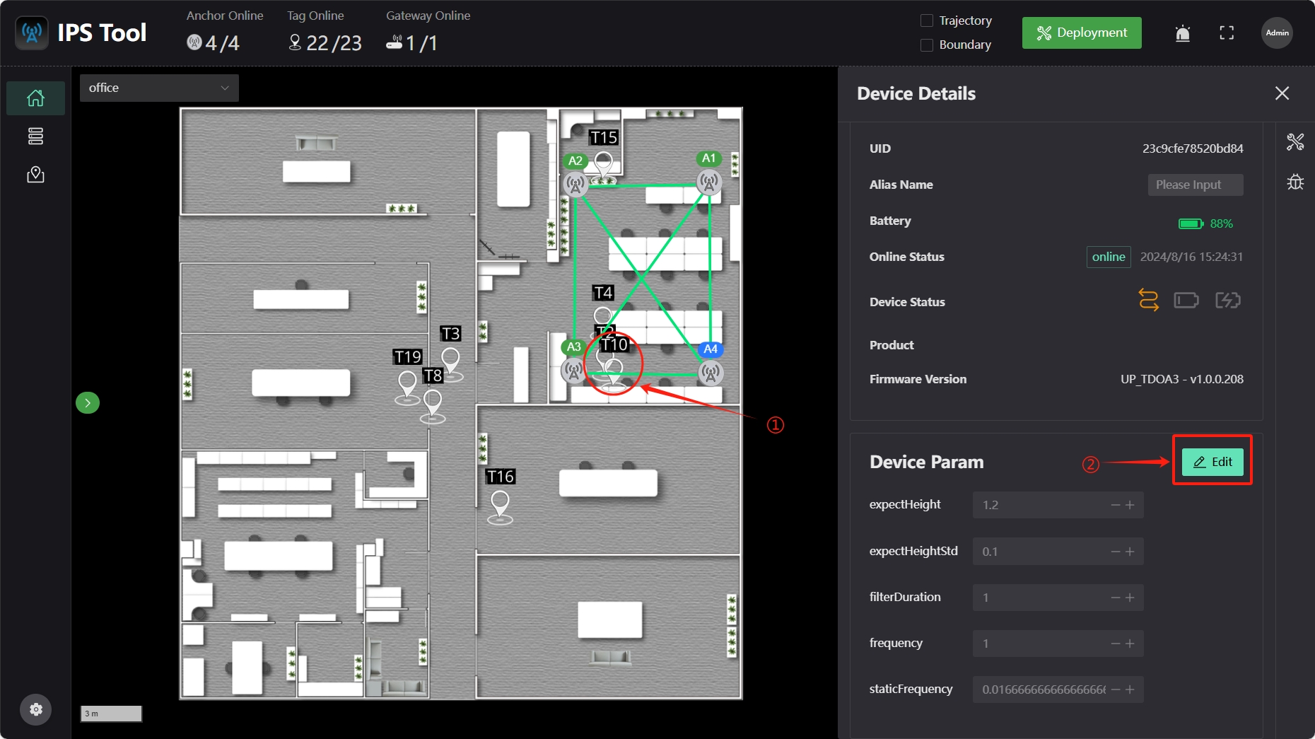
- expectHeight: Preset height (in meters) of the tag, which affects the positioning accuracy.
- expectHeightStd: Height standard deviation (in meters), indicating the fluctuation range of the tag's height, affecting positioning accuracy.
- filterDuration: Filtering duration (in seconds), impacting the smoothness of the tag's trajectory. A larger value results in smoother trajectories but increased delay.
- frequency: Tag refresh frequency (in Hertz), indicating how often the tag sends signals to the anchor. Higher values improve stability but increase power consumption.
- staticFrequency: Tag sleep period refresh frequency (in Hertz), indicating how often the tag sends signals to the anchor during sleep.
7 Static Positioning
After configuring the software, you can test the positioning effect. Place the tag within the positioning area, ensure the tag's height matches the preset range, and ensure the tag can see at least four anchors (no obstructions between the tag and the anchors).
Click the “Dashboard” icon on the left sidebar, select the corresponding map from the map menu to view the positioning results.
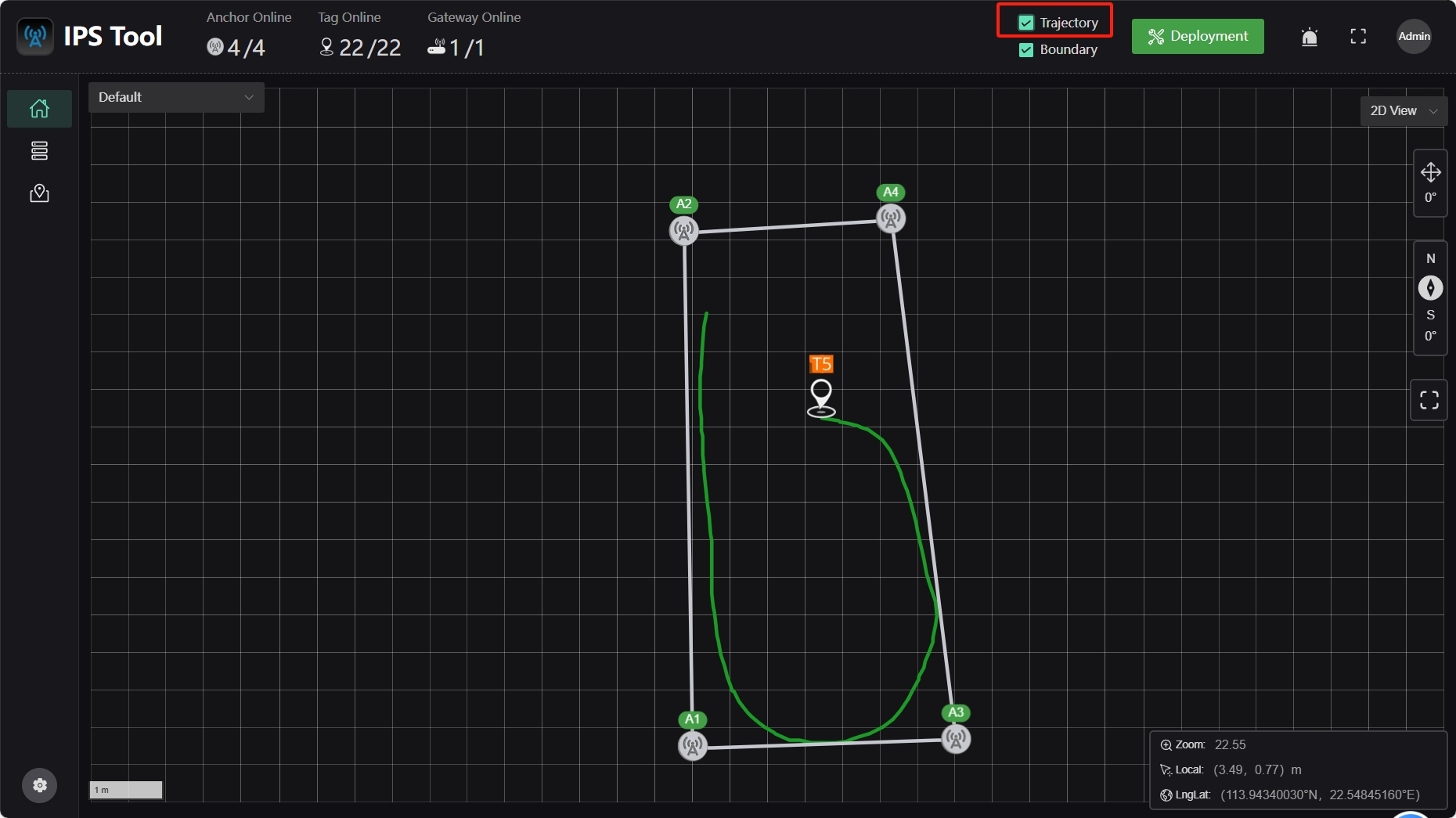
8 Dynamic Positioning
When personnel move with the tag within the positioning area, ensure the tag's height remains within the preset range and that it can see at least four anchors. Open the “Trajectory” option at the top of the software to view the tag’s movement trajectory.
9 Advanced Settings
For certain special scenarios, you can configure the corresponding parameters within the system.
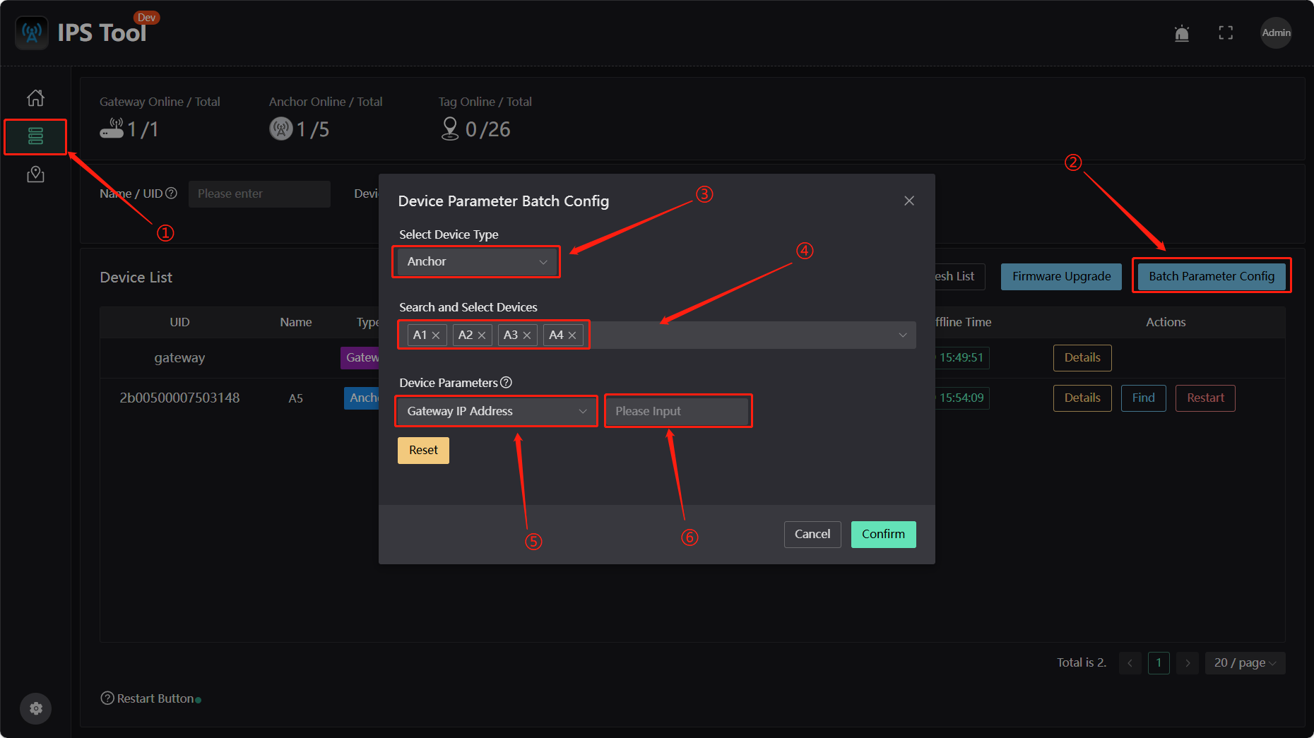
Change the Target Address of the Anchor
For scenarios with complex network environments, it is recommended that the base station adopts a setting with a fixed target IP address.
(1) Click the "Device Management" icon on the left sidebar;
(2) Click "Batch Parameter Config" on the right to modify device parameters in bulk;
(3) In the "Select Device Type" dropdown menu, select the device type as "Anchor";
(4) In the "Search and Select Devices" dropdown menu, select the anchor(s) whose target address needs to be changed;
(5) In the "Device Parameters" dropdown menu, select "Gateway IP Address";
(6) In the input field on the right, enter the target address in the correct format (e.g., 192.168.xx.254), and click "Confirm" to complete the modification.
After the modification, the anchor will first attempt to connect to the server at the target address after rebooting. If it fails to connect to the target address server, it will still connect to the server at the default address.
Add 3D Map
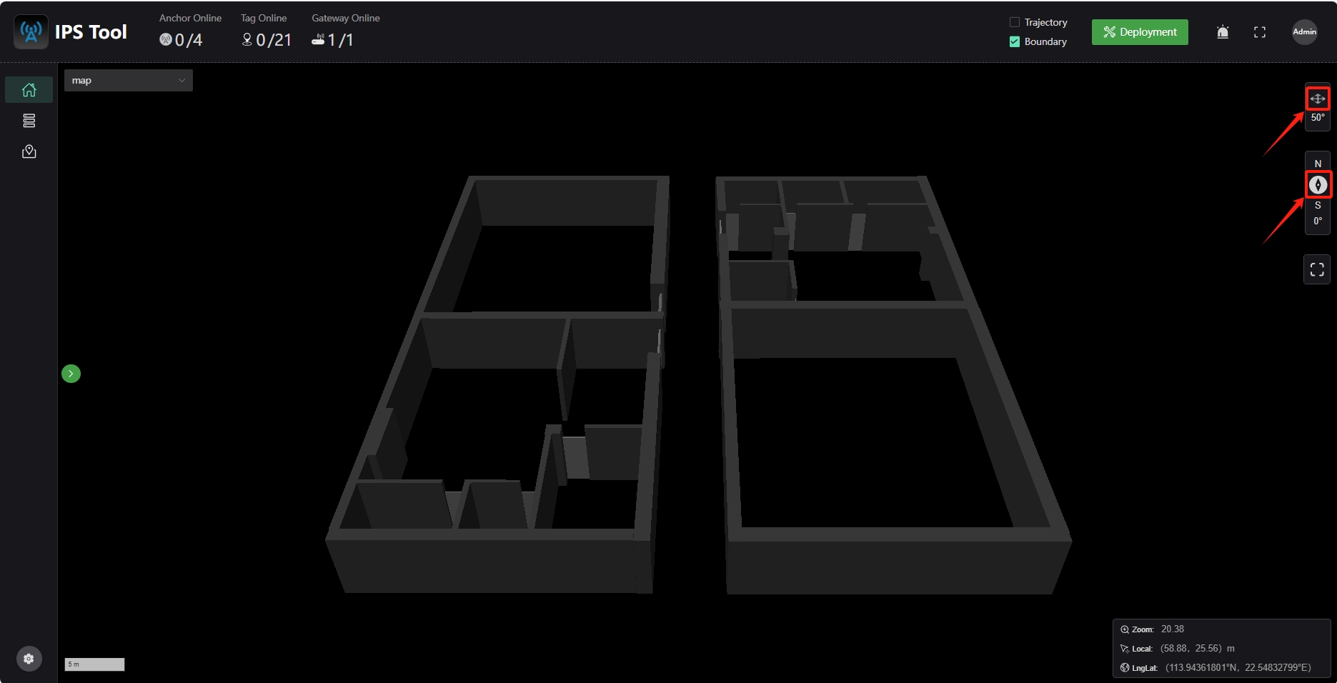
The software also supports geojson format map files. When uploading a map file, select a GeoJSON format file.Use the left mouse button to pan the map, the right mouse button to adjust the map's perspective and direction (some browsers may need to disable mouse gestures), click the cross-arrow icon in the right toolbar to reset the perspective, and click the compass icon to reset the direction.